1.4.2.8. VGA tutorial
In this tutorial, I will explain how to display a picture on a monitor using Red Pitaya. I used Xilinx Vivado 2021.1 for hardware programming with Xilinx SDK 2021.1 for software applications. The picture is just a simple matrix with “1” and “0” that represent black and white pixels. The picture can be scaled and moved and it can display different patterns.
Required hardware:
Red pitaya
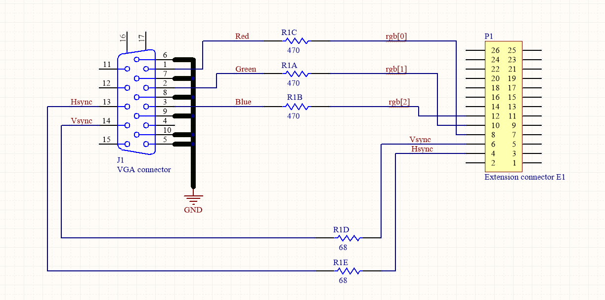
Hardware extension for VGA connector
1.4.2.8.1. Step-by-step tutorial
Open Vivado and choose to create a new project, type in the project name and project location. It is recommended to choose a location that has no spaces in the file path because Vivado can have some problems with it. Click next till you come to the page where you have to define what hardware you are using. Select “Boards” and choose Red Pitaya.
Vivado doesn’t have Red Pitaya installed by default so you have to copy board definitions from github to C:/Xilinx/Vivado/…/data/boards/board_files/.
We will use Block design to design our project because it is more manageable, but we will still have to write some VHDL code because not all the IPs we will be using are already implemented in Vivado. We will start by writing code in VHDL and creating our custom-made IPs.
First, we need to define the resolution and frequency of the monitor. Below is a table with values chosen for resolution 800 x 600, with a frequency of 50 MHz.
VGA 800 x 600 |
Number of periods |
Number of rows |
|---|---|---|
period |
H = 1040 |
V = 666 |
visible section |
Hp = 800 |
Vp = 600 |
pulse start |
Hf = 856 |
Vf = 637 |
pulse duration |
Hs = 120 |
Vs = 6 |
For displaying the picture we need a process that runs line by line on the screen. Below is the process that shifts the cursor on the screen, with a frequency of 50 MHz. (vga_vhdl.vhd)
P1: process (clk50)
begin
    if rising_edge(clk50) then
        clk_div <= not(clk_div);
        if hst_sig < (H-1) then
            hst_sig <= hst_sig +1;

        else
            hst_sig <= (others => '0');
            if vst_sig < V-1 then
                vst_sig <= vst_sig +1;
            else
                vst_sig <= (others => '0');
            end if;
        end if;
    end if;
end process;
A second process is to read the data from the array (picture.vhd).
P2: process (hst_sig, vst_sig, cx_sig, cy_sig)
begin
    if (hst_sig < Hp) and (vst_sig < Vp) then -- and en = '1' then
        if(cx_sig < Hslika) and (cy_sig < Vslika) then
            if slika(to_integer(cy_sig))( to_integer(cx_sig)) = '1' then
                rgb <= "111";
            else
                rgb <= "000";
            end if;
        else
            rgb <= "001";
        end if;
    else
        rgb <= "000";
    end if;
end process;
Image for display
type logo is array(0 to 19) of std_logic_vector(0 to 79);
signal slika: logo := (
"00000000000000000000000000000000000000000000000000000000000000000000000000000000",
"00000000100000000000000000000000000000000000000000000000000000000000000000000000",
"00000001100000000000000000000000000000000000000000000000000000000000000000000000",
"00000001000000000000000000000000000000000000000000000000000000000000000000000000",
"00000001001000000000000000000000000000000000000000000000000000000000000000000000",
"00000001001000000000000000000000000000100000000000000000000000000000000000000000",
"00000001111000000000000000000000000000100000000001001111111111111111111111111111",
"00001001111000000000000000000000000000100000000000001000000000000000000000000000",
"00010011111001000001011001111100011111100011110001011111011111100100000101111110",
"00011111111111000001100010000010100000100100001001001000000000010100000100000001",
"00000000000000000001000010000010100000100100001001001000000000010100000100000001",
"00000000000000000001000010000010100000100100001001001000001111110100000100111111",
"01111110000000000001000011111000100000100100001001001000010000010100000101000001",
"00111110011001100001000010000000100000100100001001001000010000010100000101000001",
"00111100011001100001000010000000100000100100001001001000010000010100000101000001",
"00011110000000000001000010000000100000100100001001001000010000010100000101000001",
"00011111111111000001000001111100011111100111110001000111001111110011111100111111",
"00011111111110000000000000000000000000000100000000000000000000000000000100000000",
"00000000000000000000000000000000000000000100000000000000000000000000000100000000",
"00000000000000000000000000000000000000000000000000000000000000000000000000000000");
Which looks like this:
For the monitor to work correctly, it is necessary to send synchronization pulses at the exact time, for the exact duration (vga_vhdl.vhd).
--signals to synchronize the screen
hsync <= '1' when hst_sig >= Hf and hst_sig < Hf + Hs else '0';
vsync <= '1' when vst_sig >= Vf and vst_sig < Vf + Vs else '0';
rgb_out <= rgb_in;
end Behavioral;
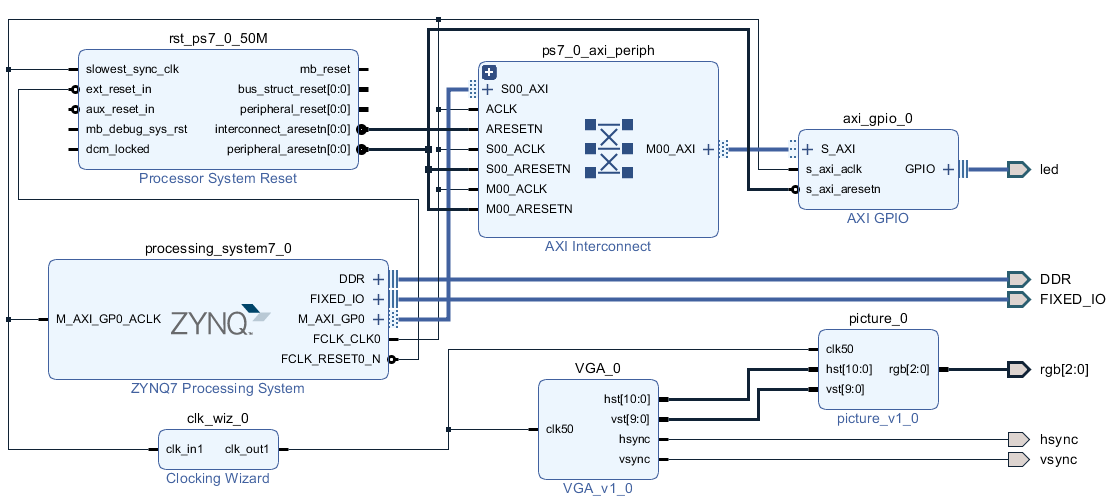
These two code files are packed in a separate IP and have the following simple block diagram.
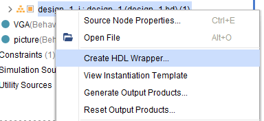
Before synthesizing the project, do not forget to create a wrapper over the block design (if it is not already created). Otherwise, the top module will not be found
Please note that you need to change the forward slashes to backward slashes on Windows.
Open Terminal or CMD and go to the .bit file location.
cd <Path/to/RedPitaya/repository>/prj/Examples/VGA_image/tmp/VGA_image/VGA_image.runs/impl_1
Send the .bit file to the Red Pitaya with the
scpcommand or use WinSCP or a similar tool to perform the operation.
scp system_wrapper.bit root@rp-xxxxxx.local:/root/VGA_image.bit
Now establish an SSH communication with your Red Pitaya and check if you have the copy VGA_image.bit in the root directory.
redpitaya> ls
Load the VGA_image.bit to xdevcfg with
redpitaya> cat VGA_image.bit > /dev/xdevcfg
The 2.00 OS uses a new mechanism of loading the FPGA. The process will depend on whether you are using Linux or Windows as the echo command functinality differs bewteen the two.
Please note that you need to change the forward slashes to backward slashes on Windows.
On Windows, open Vivado and use the TCL console. Alternatively, use Vivado HSL Command Prompt (use Windows search to find it). Navigate to the .bit file location.
On Linux, open the Terminal and go to the .bit file location.
cd <Path/to/RedPitaya/repository>/prj/Examples/VGA_image/tmp/VGA_image/VGA_image.runs/impl_1
Create .bif file and use it to generate a binary bitstream file (system_wrapper.bit.bin)
Windows (Vivado TCL console or Vivado HSL Command Prompt):
echo all:{ system_wrapper.bit } >  system_wrapper.bif
bootgen -image system_wrapper.bif -arch zynq -process_bitstream bin -o system_wrapper.bit.bin -w
Linux and Windows (WSL + Normal CMD):
echo -n "all:{ system_wrapper.bit }" >  system_wrapper.bif
bootgen -image system_wrapper.bif -arch zynq -process_bitstream bin -o system_wrapper.bit.bin -w
Using a standard command prompt, send the .bit.bin file to the Red Pitaya with the
scpcommand or use WinSCP or a similar tool to perform the operation.scp system_wrapper.bit.bin root@rp-xxxxxx.local:/root/VGA_image.bit.bin
Now establish an SSH communication with your Red Pitaya and check if you have the copy VGA_image.bit.bin in the root directory (you can use Putty or WSL).
redpitaya> lsFinally, we are ready to program the FPGA with our own bitstream file located in the /root/ folder on Red Pitaya. To program the FPGA simply execute the following line in the Red Pitaya Linux terminal that will load the VGA_image.bit.bin image into the FPGA:
redpitaya> fpgautil -b VGA_image.bit.bin
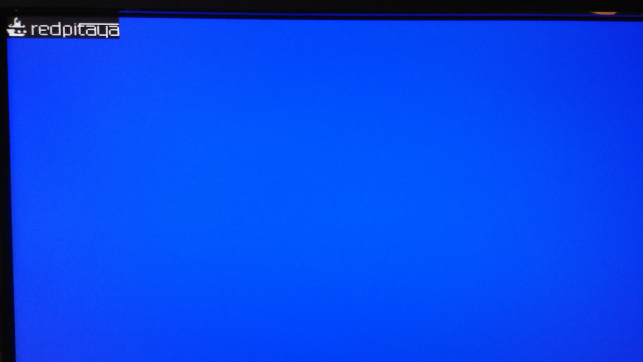
If everything is working correctly, you should see a Red Pitaya logo image displayed on your monitor after the cable is connected.
1.4.2.8.2. Automatic generation of the example from the repository
First, download the Red Pitaya FPGA Git repository to your computer and navigate to the RedPitaya-FPGA/prj/Examples folder.
Open the make_project.tcl file, uncomment the line “set project_name Vga_image”, and comment all other “set project” lines.
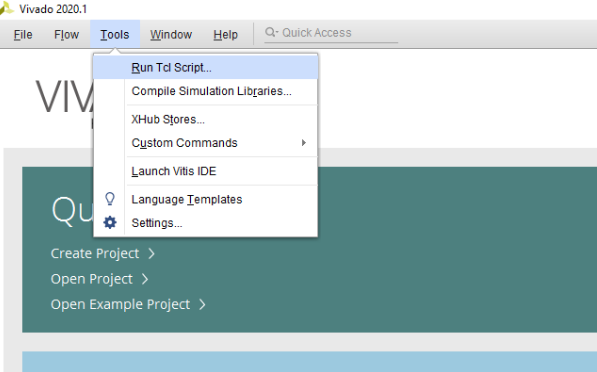
Open Vivado 2020.1 and in Vivado Tcl Console navigate to the base folder: RedPitaya-FPGA/prj/Examples.
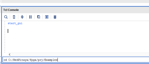
Then run the script by typing into the following command into the TCL console. If the TCL console is not open got to Tools → Run Tcl Script:
source make_project.tcl
make_project.tcl automatically generates a complete project in the RedPitaya-FPGA/prj/Examples/Vga_image/ directory.
Take a moment to examine the block design.
If the Block Design is not open, click on Flow => Open Block Design from the top menu or select Open Block Design on the left-hand side of the window (under IP INTEGRATOR). When you are ready, click Generate Bitstream at the bottom-left part of the window to generate a bitstream file.
After you confirm that both Synthesis and Implementation will be executed beforehand, the longer process starts. After successful completion of synthesis, implementation, and bitstream generation, the bit file can be found at Examples/Vga_image/tmp/Vga_image/Vga_image.runs/impl_1/system_wrapper.bit.
Finally, we are ready to program the FPGA with our own bitstream file.
1.4.2.8.3. Conclusion
Congratulations!!! You have successfully created the VGA image project!
If you want to roll back to the official Red Pitaya FPGA program, run the following command:
redpitaya> cat /opt/redpitaya/fpga/fpga_0.94.bit > /dev/xdevcfg
redpitaya> overlay.sh v0.94
or simply restart your Red Pitaya.