1.4.2.4. Stopwatch
1.4.2.4.1. Introduction
In this Red Pitaya FPGA project, we will learn about communication between the Linux processing system and the programmable logic. We will demonstrate the basic functionality with a simple FPGA project – Stopwatch.

The FPGA algorithm will be based on a 32-bit binary counter with Clock Enable (CE) and Synchronous Clear (SCLR) inputs, which we will control from the Linux side. The counter’s output value will be read with a Linux program and partially displayed with the on-board LEDs. In order to do this, we will use the standard AXI communication protocol that connects different parts of the Zynq device, such as the processing system, programmable logic, DDR memory, external peripherals, and more.
This guide assumes that you are familiar with the concepts introduced in the previous examples.
1.4.2.4.2. Verilog Module
Open one of the previous Vivado projects to get a basic block diagram.
Next, insert the binary counter IP core, if it is not already present, and add the CE and SCLR ports. This can be done by double-clicking on the binary counter IP core in our block design and selecting CE and SCLR under the Control tab. - Then add an xlslice IP block with the following dimensions: Din Width: 32, Din From: 31, Din Down To: 24.
Connect the binary counter’s CLK pin to PS’s FCLK_CLK0, the binary counter’s output to the xlslice’s input, and the xlslice’s output to the led_o external port. This last part will display 8 MSBs of the 32-bit counter on Red Pitaya’s LED bar.
If you started from Project 1, change the LEFT property of the led_o port from 0 to 7.
We are ready to insert the AXI General Purpose IO IP core (AXI GPIO) into our block design.
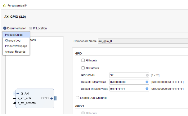
When the core is added, double-click on the block, check Enable Dual Channel and set All Inputs for the GPIO 2.
To connect the AXI GPIO to the processing system, click on Run Connection Automation on top of the block design. Select S_AXI and click OK. This will automatically create AXI Interconnect and Processor System Reset blocks.
Next, add two xlslice IP cores with 32-bit Din. xls_CE should have Din From and Din Down both set to 0 and xls_SCLR should have them both set to 1.
Connect all the blocks as shown in the figure below.
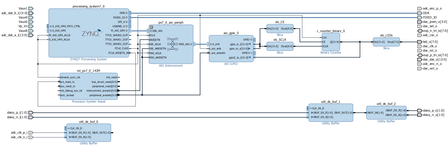
Fig. 1.15 Block Design
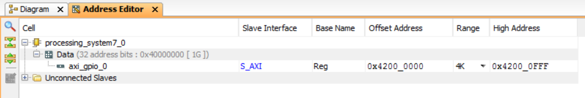
Next, we need to set the AXI GPIO core’s memory address and range. We will use this address later to access the IP core from the Linux side. On top of the window, choose the Address Editor tab and set all the values as shown below (set the address to 0x4200_0000 and the size to 4k). Remember, the address of our GPIO block is 0x4200_0000.
The FPGA program is ready. Proceed with Synthesis, Implementation, and Generation of the bitstream file. When the file is generated and copied to a folder on Red Pitaya’s Linux, write the bitstream file to programmable logic:
Please note that you need to change the forward slashes to backward slashes on Windows.
Open Terminal or CMD and go to the .bit file location.
cd <Path/to/RedPitaya/repository>/prj/Examples/Stopwatch/tmp/Stopwatch/Stopwatch.runs/impl_1
Send the .bit file to the Red Pitaya with the
scpcommand or use WinSCP or a similar tool to perform the operation.
scp system_wrapper.bit root@rp-xxxxxx.local:/root/Stopwatch.bit
Now establish an SSH communication with your Red Pitaya and check if you have the copy Stopwatch.bit in the root directory.
redpitaya> ls
Load the Stopwatch.bit to xdevcfg with
redpitaya> cat Stopwatch.bit > /dev/xdevcfg
The 2.00 OS uses a new mechanism of loading the FPGA. The process will depend on whether you are using Linux or Windows as the echo command functinality differs bewteen the two.
Please note that you need to change the forward slashes to backward slashes on Windows.
On Windows, open Vivado and use the TCL console. Alternatively, use Vivado HSL Command Prompt (use Windows search to find it). Navigate to the .bit file location.
On Linux, open the Terminal and go to the .bit file location.
cd <Path/to/RedPitaya/repository>/prj/Examples/Stopwatch/tmp/Stopwatch/Stopwatch.runs/impl_1
Create .bif file and use it to generate a binary bitstream file (system_wrapper.bit.bin)
Windows (Vivado TCL console or Vivado HSL Command Prompt):
echo all:{ system_wrapper.bit } >  system_wrapper.bif
bootgen -image system_wrapper.bif -arch zynq -process_bitstream bin -o system_wrapper.bit.bin -w
Linux and Windows (WSL + Normal CMD):
echo -n "all:{ system_wrapper.bit }" >  system_wrapper.bif
bootgen -image system_wrapper.bif -arch zynq -process_bitstream bin -o system_wrapper.bit.bin -w
Using a standard command prompt, send the .bit.bin file to the Red Pitaya with the
scpcommand or use WinSCP or a similar tool to perform the operation.scp system_wrapper.bit.bin root@rp-xxxxxx.local:/root/Stopwatch.bit.bin
Now establish an SSH communication with your Red Pitaya and check if you have the copy Stopwatch.bit.bin in the root directory (you can use Putty or WSL).
redpitaya> lsFinally, we are ready to program the FPGA with our own bitstream file located in the /root/ folder on Red Pitaya. To program the FPGA simply execute the following line in the Red Pitaya Linux terminal that will load the Stopwatch.bit.bin image into the FPGA:
redpitaya> fpgautil -b Stopwatch.bit.bin
To write or read from our FPGA program we will use Red Pitaya’s monitor tool, available in Red Pitaya’s Linux. Try the following commands:
monitor 0x42000000 1  # write: start, SCLR = 0, CE = 1
monitor 0x42000000 0  # write: stop,  SCLR = 0, CE = 0
monitor 0x42000000 2  # write: clear, SCLR = 1, CE = 0

monitor 0x42000000  # read: cfg  on GPIO1
monitor 0x42000008  # read: data on GPIO2
Great, we have created a stopwatch with a resolution of 8 ns! Using the AXI communication protocol, we can easily access our GPIO IP core. More details about the GPIO core can be found in the Vivado AXI reference guide. If you would like to know how much time has passed between start and stop in seconds and not in the number of clock cycles, you can use the following programs to write, read, and convert data.
1.4.2.4.3. C Program
This program, based on Pavel Demin’s code, can also be a useful template for more advanced applications where you need to set several parameters and read large amounts of data generated on FPGA.
1.4.2.4.3.1. stopwatch.c:
#include <stdio.h>
#include <stdint.h>
#include <unistd.h>
#include <sys/mman.h>
#include <fcntl.h>
#include <stdlib.h>

int main(int argc, char **argv)
{
    int fd;
    float wait_time;
    uint32_t count;
    void *cfg;
    char *name = "/dev/mem";
    const int freq = 125000000;         // Hz

    if (argc == 2) wait_time = atof(argv[1]);
    else wait_time = 1.0;

    if((fd = open(name, O_RDWR)) < 0) {
        perror("open");
        return 1;
    }
    cfg = mmap(NULL, sysconf(_SC_PAGESIZE), /* map the memory */
                PROT_READ|PROT_WRITE, MAP_SHARED, fd, 0x42000000);

    *((uint32_t *)(cfg + 0)) = 2;       // clear timer
    *((uint32_t *)(cfg + 0)) = 1;       // start timer

    sleep(wait_time);                   // wait for [wait_time] seconds

    *((uint32_t *)(cfg + 0)) = 0;       // stop timer

    count = *((uint32_t *)(cfg + 8));   // get binary counter output

    printf("Clock count: %5d, calculated time: %5f s\n",
            count, (double)count/freq);

    munmap(cfg, sysconf(_SC_PAGESIZE));
    return 0;
}
The stopwatch.c program maps the memory at a given address to a cfg pointer. By writing an appropriate 32-bit value to this pointer, the code first clears the counter by setting SCLR (2nd bit), then starts the count by setting CE (1st bit). After wait_time in seconds, the counter is stopped by clearing the CE bit. To read the counter’s output value, we need to access the second port of the GPIO IP core. According to the GPIO documentation:
The address of the second port is shifted by 8 (0x4200_0008). At the end, the counter output value is scaled by the FCLK_CLK0 frequency and printed on the screen.
Next, copy the stopwatch.c program found in the Stopwatch folder to Red Pitaya’s Linux. Compile and execute the program as shown here:
gcc -o stopwatch stopwatch.c
./stopwatch 5   # wait for 5 s
1.4.2.4.4. Python Program
You can also achieve the same functionality with Python; after you have written the FPGA, connect to your Red Pitaya through the browser and navigate to the Jupyter Notebook application, which can be found in Development.
Open the Jupyter Notebook application, create a new notebook, copy the code below, save it, and finally execute it.
import mmap
import os
import time
import numpy as np

axi_gpio_regset = np.dtype([
    ('gpio1_data'   , 'uint32'),
    ('gpio1_control', 'uint32'),
    ('gpio2_data'   , 'uint32'),
    ('gpio2_control', 'uint32')
])

## Change the FPGA image ##

os.system('cat /root/Stopwatch.bit > /dev/xdevcfg')    # OS 1.04 or older
# os.system('fpgautil -b /root/Stopwatch.bit.bin')     # OS 2.00 and above

memory_file_handle = os.open('/dev/mem', os.O_RDWR)
axi_mmap = mmap.mmap(fileno=memory_file_handle, length=mmap.PAGESIZE, offset=0x40000000)
axi_numpy_array = np.recarray(1, axi_gpio_regset, buf=axi_mmap)
axi_array_contents = axi_numpy_array[0]

freq = 125000000 #FPGA Clock Frequency Hz

axi_array_contents.gpio1_data = 0x02 #clear timer
axi_array_contents.gpio1_data = 0x01 #start timer
time.sleep(34.2) # Count to the maximim LED (8 MSB value)
axi_array_contents.gpio1_data = 0x00 #stop timer
print("Clock count: ", axi_array_contents.gpio2_data, " calculated time: ", axi_array_contents.gpio2_data/freq, " Seconds")
1.4.2.4.5. Changing the FPGA Fabric Clock Speed
Interestingly, FCLK_CLK0 has a frequency of 124.99875 MHz (= 3.75*33.333 MHz). This is the default Red Pitaya frequency generated by IO PLL using a 33.333 MHz external clock (PS_CLK).
The following terminal commands can be used to change the PL fabric clock speed. The script needs root access. The clock frequency can be set from 100000 to 2500000000. Clock speeds above 300000 give better timing results from a Jupyter Notebook. 125000000 is the default.
devcfg=/sys/devices/soc0/amba/f8007000.devcfg
test -d $devcfg/fclk/fclk0 || echo fclk0 > $devcfg/fclk_export
echo 0 > $devcfg/fclk/fclk0/enable
echo 2500000000 > $devcfg/fclk/fclk0/set_rate
echo 1 > $devcfg/fclk/fclk0/enable
1.4.2.4.6. Automatic generation of an example from the repository
Move to folder RedPitaya-FPGA/prj/Examples. Uncomment the line “set project_name Stopwatch” and comment all files in the make_project.tcl file. Open Vivado and in Vivado Tcl Console navigate to the base folder: RedPitaya-FPGA/prj/Examples.
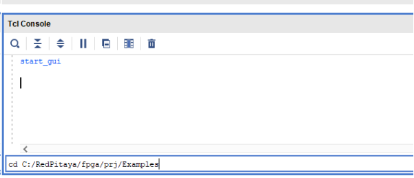
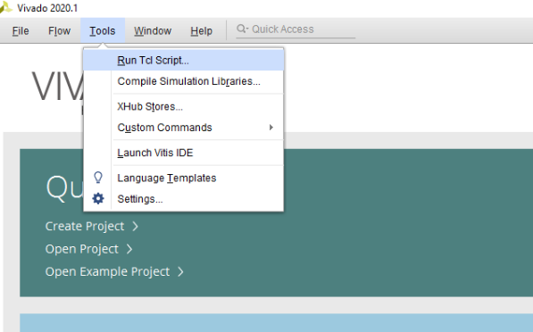
Then run the script source make_project.tcl. Tools → Run Tcl Script
make_project.tcl automatically generates a complete project in the RedPitaya-FPGA/prj/Examples/Stopwatch/ directory. Take a moment to examine the block design. If the block design is not open, click on Open Block Design on the left-hand side of the window. When you are ready, click Generate Bitstream at the bottom-left part of the window to generate a bitstream file. After you confirm that both Synthesis and Implementation will be executed beforehand the longer process starts. After successful completion of synthesis, implementation, and bitstream generation, the bit file can be found at Examples/Stopwatch/tmp/Stopwatch/Stopwatch.runs/impl_1/system_wrapper.bit
Follow the instructions above to change the FPGA image on the Red Pitaya.
1.4.2.4.7. Conclusion
Congratulations! We have created another simple project where we learned how to communicate between our FPGA program and Linux running on Red Pitaya’s Zynq7 ARM processor.
If you want to roll back to the official Red Pitaya FPGA program, run the following command:
redpitaya> cat /opt/redpitaya/fpga/fpga_0.94.bit > /dev/xdevcfg
redpitaya> overlay.sh v0.94
or simply restart your Red Pitaya.