1.4.2.2. Simple LED blinker
1.4.2.2.1. Introduction
In this section we will learn how to create a simple LED blink program using IP cores in Vivado 2020.1. As this is the first step on our way to become an FPGA expert, we will not overcomplicate things but rather start with an already created project and explain its functionality.
At this stage it is assumed that Red Pitaya is successfully connected the local network with an established SSH (or Putty) connection. If not, follow the link to the Red Pitaya’s quick-start instructions.
1.4.2.2.2. Generation of an example from the repository
First, download the Red Pitaya FPGA Git repository to your computer and navigate to the RedPitaya-FPGA/prj/Examples folder.
Open the make_project.tcl file, uncomment the line “set project_name Led_blink”, and comment all other “set project” lines.
Open Vivado 2020.1 and in Vivado Tcl Console navigate to the base folder: RedPitaya-FPGA/prj/Examples.
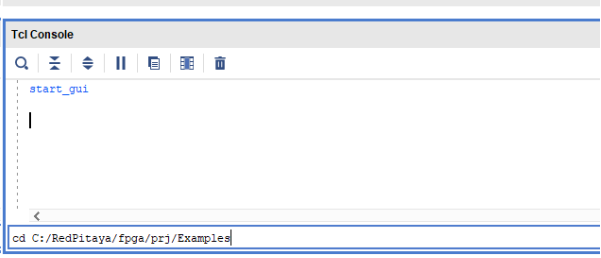
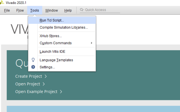
Then run the script by typing into the following command into the TCL console. If the TCL console is not open got to Tools → Run Tcl Script:
source make_project.tcl
make_project.tcl automatically generates a complete project in the RedPitaya-FPGA/prj/Examples/Led_blink/ directory.
Take a moment to examine the block design.
If the Block Design is not open, click on Flow => Open Block Design from the top menu or select Open Block Design on the left-hand side of the window (under IP INTEGRATOR). When you are ready, click Generate Bitstream at the bottom-left part of the window to generate a bitstream file.
After you confirm that both Synthesis and Implementation will be executed beforehand, the longer process starts. After successful completion of synthesis, implementation, and bitstream generation, the bit file can be found at Examples/Led_blink/tmp/Led_blink/Led_blink.runs/impl_1/system_wrapper.bit.
Finally, we are ready to program the FPGA with our own bitstream file.
Please note that you need to change the forward slashes to backward slashes on Windows.
Open Terminal or CMD and go to the .bit file location.
cd <Path/to/RedPitaya/repository>/prj/Examples/Led_blink/tmp/Led_blink/Led_blink.runs/impl_1
Send the .bit file to the Red Pitaya with the
scpcommand or use WinSCP or a similar tool to perform the operation.
scp system_wrapper.bit root@rp-xxxxxx.local:/root/Led_blink.bit
Now establish an SSH communication with your Red Pitaya and check if you have the copy Led_blink.bit in the root directory.
redpitaya> ls
Load the Led_blink.bit to xdevcfg with
redpitaya> cat Led_blink.bit > /dev/xdevcfg
The 2.00 OS uses a new mechanism of loading the FPGA. The process will depend on whether you are using Linux or Windows as the echo command functinality differs bewteen the two.
Please note that you need to change the forward slashes to backward slashes on Windows.
On Windows, open Vivado and use the TCL console. Alternatively, use Vivado HSL Command Prompt (use Windows search to find it). Navigate to the .bit file location.
On Linux, open the Terminal and go to the .bit file location.
cd <Path/to/RedPitaya/repository>/prj/Examples/Led_blink/tmp/Led_blink/Led_blink.runs/impl_1
Create .bif file and use it to generate a binary bitstream file (system_wrapper.bit.bin)
Windows (Vivado TCL console or Vivado HSL Command Prompt):
echo all:{ system_wrapper.bit } >  system_wrapper.bif
bootgen -image system_wrapper.bif -arch zynq -process_bitstream bin -o system_wrapper.bit.bin -w
Linux and Windows (WSL + Normal CMD):
echo -n "all:{ system_wrapper.bit }" >  system_wrapper.bif
bootgen -image system_wrapper.bif -arch zynq -process_bitstream bin -o system_wrapper.bit.bin -w
Using a standard command prompt, send the .bit.bin file to the Red Pitaya with the
scpcommand or use WinSCP or a similar tool to perform the operation.scp system_wrapper.bit.bin root@rp-xxxxxx.local:/root/Led_blink.bit.bin
Now establish an SSH communication with your Red Pitaya and check if you have the copy Led_blink.bit.bin in the root directory (you can use Putty or WSL).
redpitaya> lsFinally, we are ready to program the FPGA with our own bitstream file located in the /root/ folder on Red Pitaya. To program the FPGA simply execute the following line in the Red Pitaya Linux terminal that will load the Led_blink.bit.bin image into the FPGA:
redpitaya> fpgautil -b Led_blink.bit.bin
Now, you should see the 0th LED blink. Don’t worry, you did not destroy your Red Pitaya. If you want to roll back to the official Red Pitaya FPGA program run
redpitaya> cat /opt/redpitaya/fpga/fpga_0.94.bit > /dev/xdevcfg
redpitaya> overlay.sh v0.94
or simply restart your Red Pitaya.
1.4.2.2.3. Description
Congratulations, you have just programmed your FPGA! But now, you are probably asking yourself what just happened? Let us quickly go though the most important steps to understand how we made one of the LEDs blink.
In this project, we did not need to write any hardware description language (HDL) code. Instead, we use IP cores, which are already packaged code in Vivado, and connect them in the IP Integrator. The IP integrator (Block Design) is a useful addition to Vivado, which offers a visual representation of our program flow. It also helps us connect relevant blocks and navigate between our code. We will learn how to add our code as a block in the block design in the next project.
During the project creation, the script specifies Red Pitaya’s FPGA part name xc7z010clg400-1. This information is important for synthesis, implementation, and bitstream generation. Later, the script creates Red Pitaya specific external ports related to the chip pins as described in the constraint file shown in the Sources tab under Constraints/constrs_1/port.xdc (or Led_blink/cfg/port.xdc).
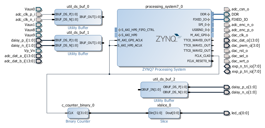
Fig. 1.11 Block Design of the LED blink project
Next, the script adds the Zynq processing_system7 block with Red Pitaya specific settings set by Led_blink/cfg/red_pitaya.xml. This IP core represents an interface between the processing system used for running Linux and the programmable logic (FPGA). There are many useful shared ports, such as a clock (FCLK_CLK0), and communication interface ports (M_AXI_GPIO), which we will use in future projects.
A quick introduction to processing_system7 can be found on the Xilinx’s video page.
Some of the external ports are differential and therefore need to be properly handled. For this reason, the script adds three buffers with differential ports (IBUFDS type) and connects them to those external ports (adc_clk_*, 2 x dasy_*). These buffers play no role in our LED blinking algorithm but should be there for proper implementation. To achieve LED blinking with an interval of around 1 s, we use the FCLK_CLK0 clock from the processing_system7 block running at 125 MHz. To reduce the frequency from 125 MHz to 1 Hz, we connect FCLK_CLK0 to the 32-bit Binary Counter block and then to the Slice block, which selects only the 26th bit.
The time interval of the 26th bit is therefore
The 26-th bit is finally wired to the led (0), which makes LED(0) blink on the Red Pitaya board. You can change the size of the Binary Counter or the Slice position by double clicking on the block and changing its parameters. The connections (wires) are simply made by clicking on a free port and dragging it to another port or wire. IP Integrator will check port types and sizes and allow a connection only if these are compatible. Sometimes IP Integrator offers a Run Block Automation option on top of the Block Design area which can automatically connects ports and even adds additional blocks when needed. Further information on how to use Vivado’s IP Integrator (Block Design) can be found in Xilinx documentation.
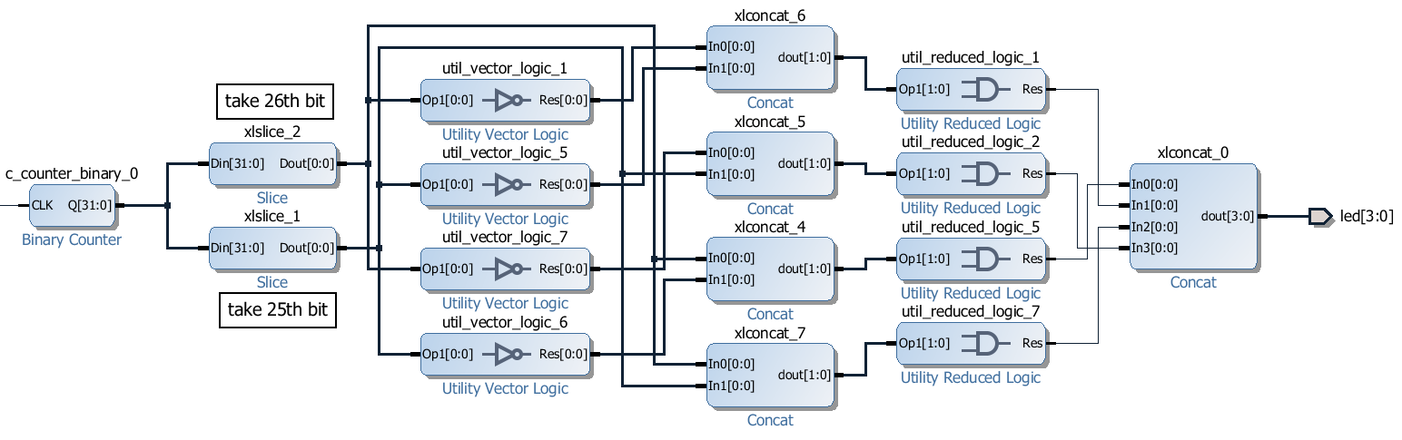
1.4.2.2.4. Extension 1
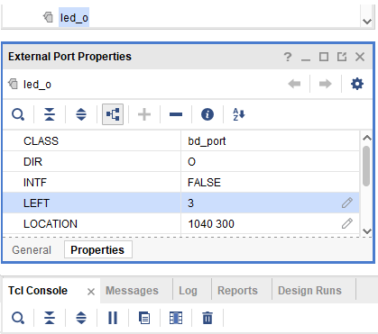
One can play and create more exciting blinking LED sequences. For fun, try changing the blocks responsible for blinking to the following diagram and see what happens. For this, you can use a number of available Xilinx IP cores when right clicking on the empty space on the Block Design and choosing Add IP…. Don’t forget to change the LEFT attribute of the LED port to 3.
1.4.2.2.5. Extension 2
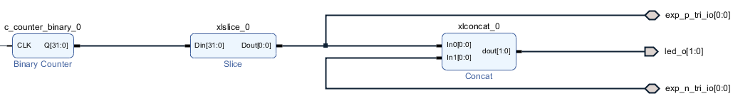
Instead of connecting our periodic signal to the LED (led_o [0]), we can also connect it to an extension port (exp_tri_p_io [0]) linked with the DIO0_p pin on the extension connector E1. Since the exp_tri_p_io is bidirectional, we cannot simply wire it in the block design. There are two ways to solve this problem. (1) Remove the exp_tri_p_io port and replace it with one that has the same name but a different direction. You can create the port by right-clicking on the block design area and selecting Create Port… or modify a tcl command found on line 38 in the cfg/port.tcl file and execute it in the tcl console. (2) The second solution is much simpler. Use the following tcl command to connect your signal to the desired bidirectional port (exp_tri_p_io).
connect_bd_net [get_bd_pins xlconcat_0/In0] [get_bd_pins exp_p_tri_io]
We can check if the DIO0_p pin has a periodic signal by connecting it to the neighbouring pin DIO0_n on the E1 connector with an external wire. We can use the same technique to connect the corresponding exp_tri_n_io[0] port to the second LED in the block design. Check the Extension connector’s manual to locate the appropriate pins. If all goes well, as soon as you connect DIO0_p and DIO0_n pins, two LEDs should blink at the same time. Be careful when connecting any external signals to the E1 connector. Always check the voltage requirements first. The following schematic shows how to assemble the block design.
1.4.2.2.6. Conclusion
This concludes our first project. We have learned how to install the Zynq FPGA Vivado development suite and created a simple project where we ran the synthesis, the implementation, and generated a bitstream file. We uploaded the bit-file to Red Pitaya’s Linux and used it to configure the programmable logic. Since here all Red-Pitaya specific components are present, LED blinker is an ideal starting point for more advanced projects.
If you want to roll back to the official Red Pitaya FPGA program, run the following command:
redpitaya> cat /opt/redpitaya/fpga/fpga_0.94.bit > /dev/xdevcfg
redpitaya> overlay.sh v0.94
or simply restart your Red Pitaya.