2.7. Analog addition and subtraction
2.7.1. Introduction
In this course, we will dive into the fundamental concepts of adding and subtracting using operational amplifiers (OpAmps). These concepts serve as the building blocks of arithmetic operations, and their understanding is essential to comprehend more advanced electrical circuits. While we have covered voltage dividers, multipliers, and inverters, which involve mathematical operations such as multiplication and division, the focus of this course will be on the basic algebraic operations of addition and subtraction. We will demonstrate how OpAmps can be employed as effective tools for implementing these operations in electrical circuits.
2.7.2. Addition
In primary school you learned to add numbers before subtraction, and we will follow the same steps here. Addition first. We want a circuit that will be able to implement the following function:
\[U_{out}=a \cdot U_1 + b \cdot U_2\]
To make things easier to understand, let’s first take a look at how we would implement just one part of this equation, \(U_{out}=a \cdot U_1\) for example. One circuit that matches this equation would be an inverting amplifier.

It implements the function \(U_{out}=-\frac{R_2}{R_1} \cdot U_1\). Now let’s make a thought experiment. If we added another voltage source, U2, connected to the inverting input of OpAmp through a capacitor, and U2 was at zero volts… What would happen? Output voltage wouldn’t change since inverting input is a virtual ground. But if we set U1 to 0V and U2 to something different, implemented function would be \(U_{out}=-\frac{R_2}{R_3} \cdot U_2\).

Did you read the previous course on superposition? If you did, you must have already guessed what direction we’re heading. Superposition. Function \(U_{out}=a \cdot U_1 + b \cdot U_2\) is a textbook example of a linear combination of multiple inputs, making it suitable for solving with superposition theorem.
We have acquired knowledge on how to add two voltage sources together using operational amplifiers (OpAmps). However, it should be noted that this principle can be extended to include any number of additional voltage sources. By connecting these voltage sources, each with their respective resistor, to the inverting node of the OpAmp, the resulting function will remain consistent with expectations. This demonstrates the versatility of OpAmps and their ability to add an indefinite number of voltages.
2.7.3. Addition experiment
To validate the principle of adding an indefinite number of voltage sources using operational amplifiers (OpAmps), it is recommended to perform an experiment using a Red Pitaya. While the Red Pitaya has only two outputs, one can still implement a simple inverting adder circuit for two inputs. To expand the circuit to include additional signals, one can introduce external voltage sources or even add a voltage divider to generate a customized voltage level. This experiment will help to confirm the validity of the principle and demonstrate the versatility of OpAmps in adding multiple voltages (for the sake of simplicity of this experiment you can use our 3.3V ,5V and -4V pins, so you don’t have to deal with the voltage devider).
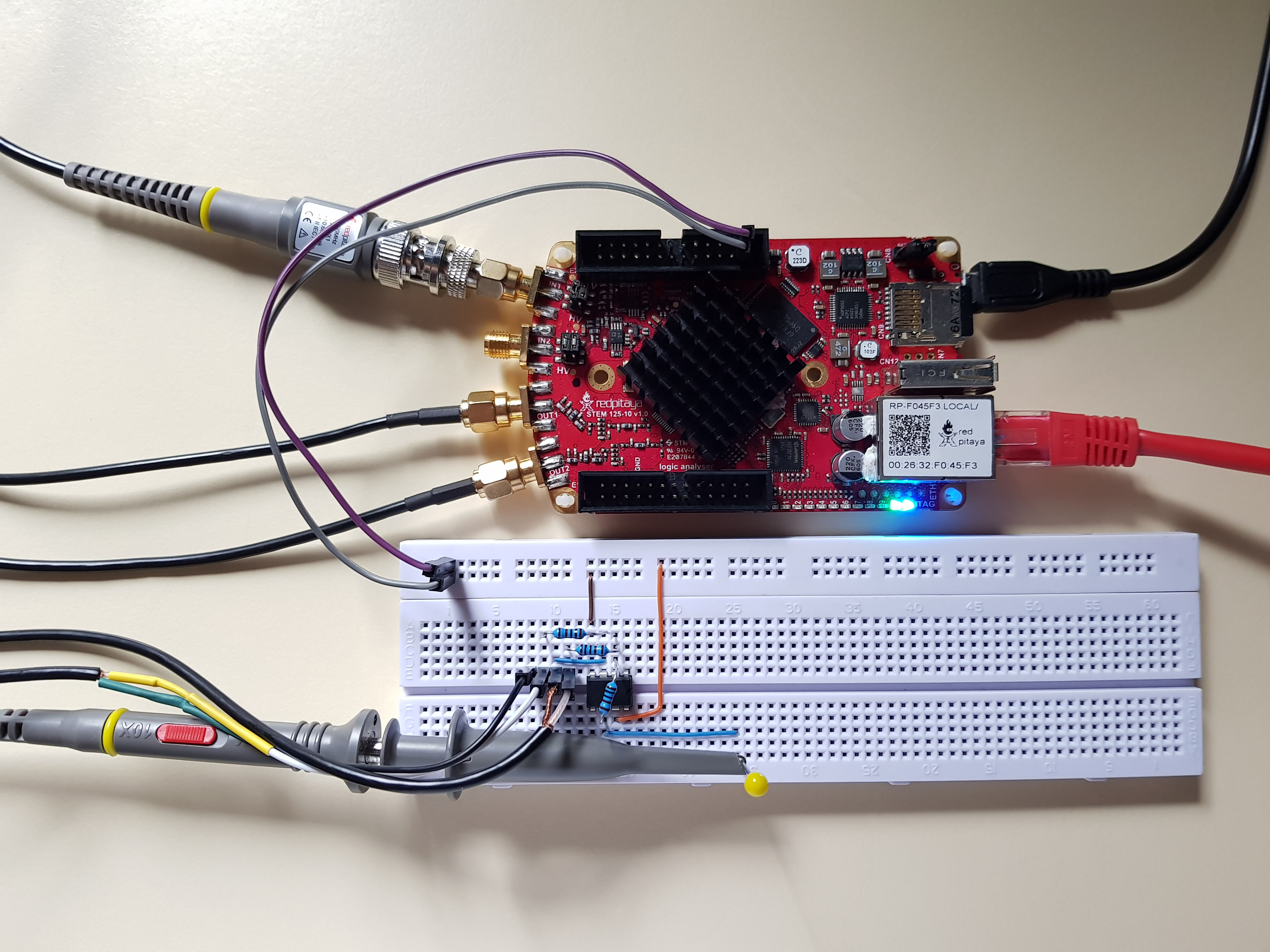
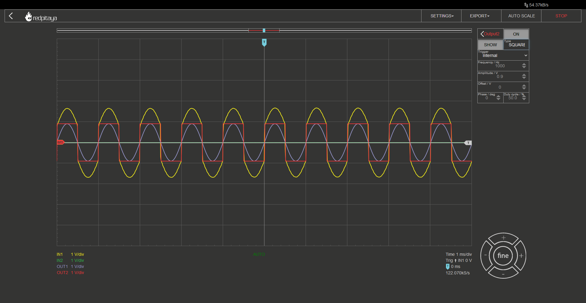
Setup is the same as usual. Input probe in 10x mode, both in hardware and in software. All resistors were 1 kOhm. The following Screencapture is with both output channels enabled, one is outputting a sine, and the other a square wave function. I will let you decide of the output function, yellow, is a, inverted sum of the two inputs.
Having established the functionality of an inverting adder circuit using operational amplifiers (OpAmps), the task at hand is to design a noninverting adder circuit. However, it is crucial to note that connecting two inputs directly can lead to a short circuit, and potentially damage the Red Pitaya. To avoid this, resistors should be introduced, with a recommended value of 1k or preferably 10kOhm. The circuit can be built using a noninverting amplifier and taking advantage of superposition. It is worth mentioning that an inverter should not be added to the output to achieve the desired functionality.
2.7.4. Subtraction
The concept of subtraction can be boiled down to the inversion of the second operand and addition of the two operands. To achieve this in an electrical circuit, a combination of inverting and noninverting amplifiers can be employed, much like in the case of addition. However, it is worth noting that using a dedicated inverting amplifier to invert one input voltage is not the most elegant approach. Instead, we can adopt a more sophisticated solution, which involves the use of the following technique:

The U2 branch of the circuit is relatively straightforward. When U1 is set to zero, the circuit behaves similarly to a standard inverting amplifier. However, when U2 is set to zero, the analysis becomes more complex. It is essential to remember that during normal operation, the inputs of the OpAmp are at the same voltage. As a result, we get the following two equations:
\[U_+=U_1 \cdot \frac{R_4}{R_3+R_4}\]\[U_-=U_{OUT} \frac{R_1}{R_1+R_3}\]
When we combine them, we get:
\[U_{OUT}=U_1 \frac{R_4}{R_2+R_4} \frac{R_1+R_3}{R_1}\]
The circuit functions as a nonstandard noninverting amplifier, and while it may deviate from the standard approach, the equations derived from its analysis are still valid. By selecting components such that R1 is equal to R2, and R3 is equal to R4, we can simplify the equation to the following form:
\[U_{OUT} = \frac{R_3}{R_1}(U_1-U_2 )\]
The circuit above is commonly known as a differential amplifier.
2.7.5. Differential amplifier experiment
Let’s connect the OpAmp in differential orientation to Red Pitaya as shown in the picture bellow, so we can watch what happens to our input signal, when driven through the differential amplifier.
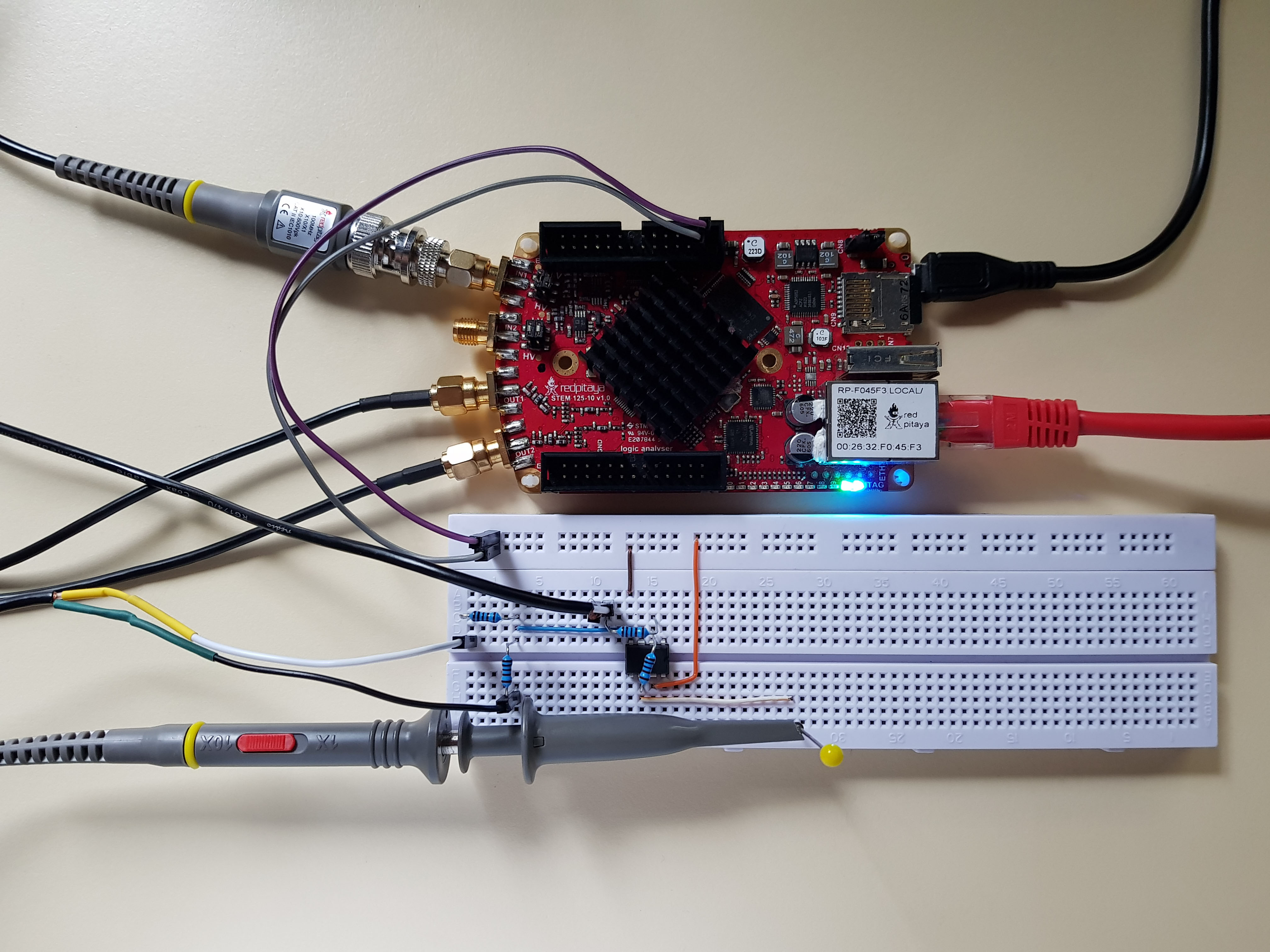
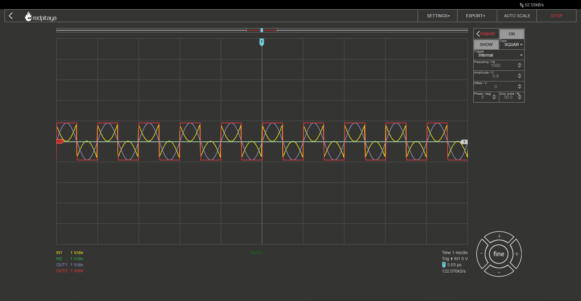
Same as before, probe in 10x mode, one output is sine, the other square wave, all resistors are 1k, and this is the result:
2.7.6. Conclusion
By combining the concepts of inverting and noninverting amplifiers, we have successfully demonstrated the implementation of all basic arithmetic operations in analog circuits. This includes addition, subtraction, multiplication, and division. The latter can be achieved either by using resistors to divide by a constant or by multiplying with an inverse number to divide by an arbitrary value. Although there also exists a circuit for arbitrary division, we will not go into further detail on this topic. I hope that you found this course engaging and informative, and that you have gained valuable knowledge and skills from it.
Written by Luka Pogačnik Edited by Andraž Pirc
This teaching material was created by Red Pitaya & Zavod 404 in the scope of the Smart4All innovation project.