2.10. Schmitt triggers
2.10.1. Introduction
Comparators are electronic devices that are commonly used in circuits to compare two voltage levels. When the voltage level at the noninverting input is greater than that at the inverting input, the output of the comparator is driven to positive saturation. Conversely, when the voltage level at the inverting input is greater than that at the noninverting input, the output is driven to negative saturation. However, if the voltage levels at the inputs are very close, the output can become unstable and oscillate between the two saturation voltages, especially if the noninverting input is subject to noise. To overcome this issue, a deadzone can be introduced, which prevents the comparator from toggling its output when the input voltage changes within a certain range. This helps to improve the stability and accuracy of the circuit.
2.10.2. Comparators
Let’s start this course off by refreshing our knowledge about comparators. They are essentially OpAmps that sacrifice their stability for faster switching speed. Much in the same way as OpAmps, their output is the voltage difference between noninverting and inverting inputs, multiplied by a huge factor.
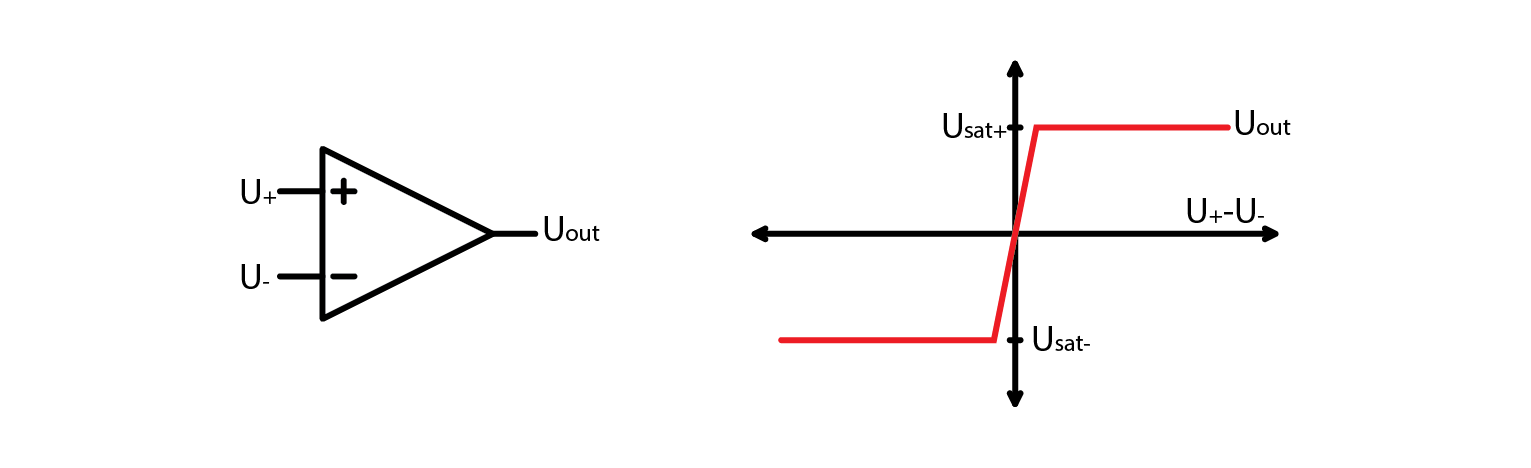
For almost any real application, their characteristic can be described as such:
\[U_{out}= U_{sat+} \; when \; U_{+} > U_{-}\]\[U_{out}= U_{sat-} \; when \; U_{+} < U_{-}\]
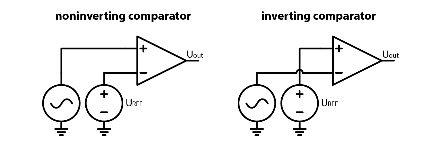
Depending on which input (inverting or noninverting) we select to be reference input, we can obtain an inverting or a noninverting comparator as shown on the image below.
2.10.3. Modifying a comparator
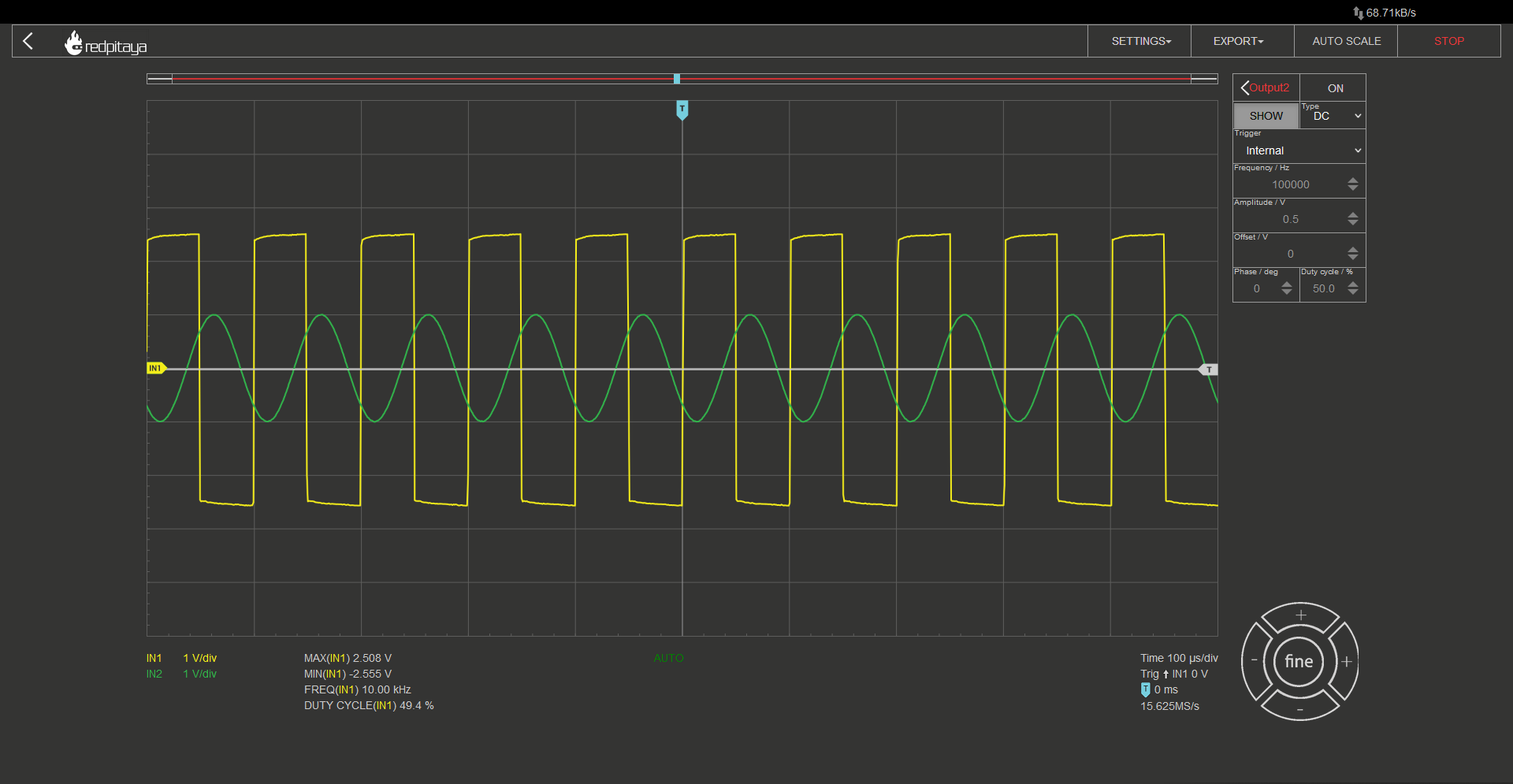
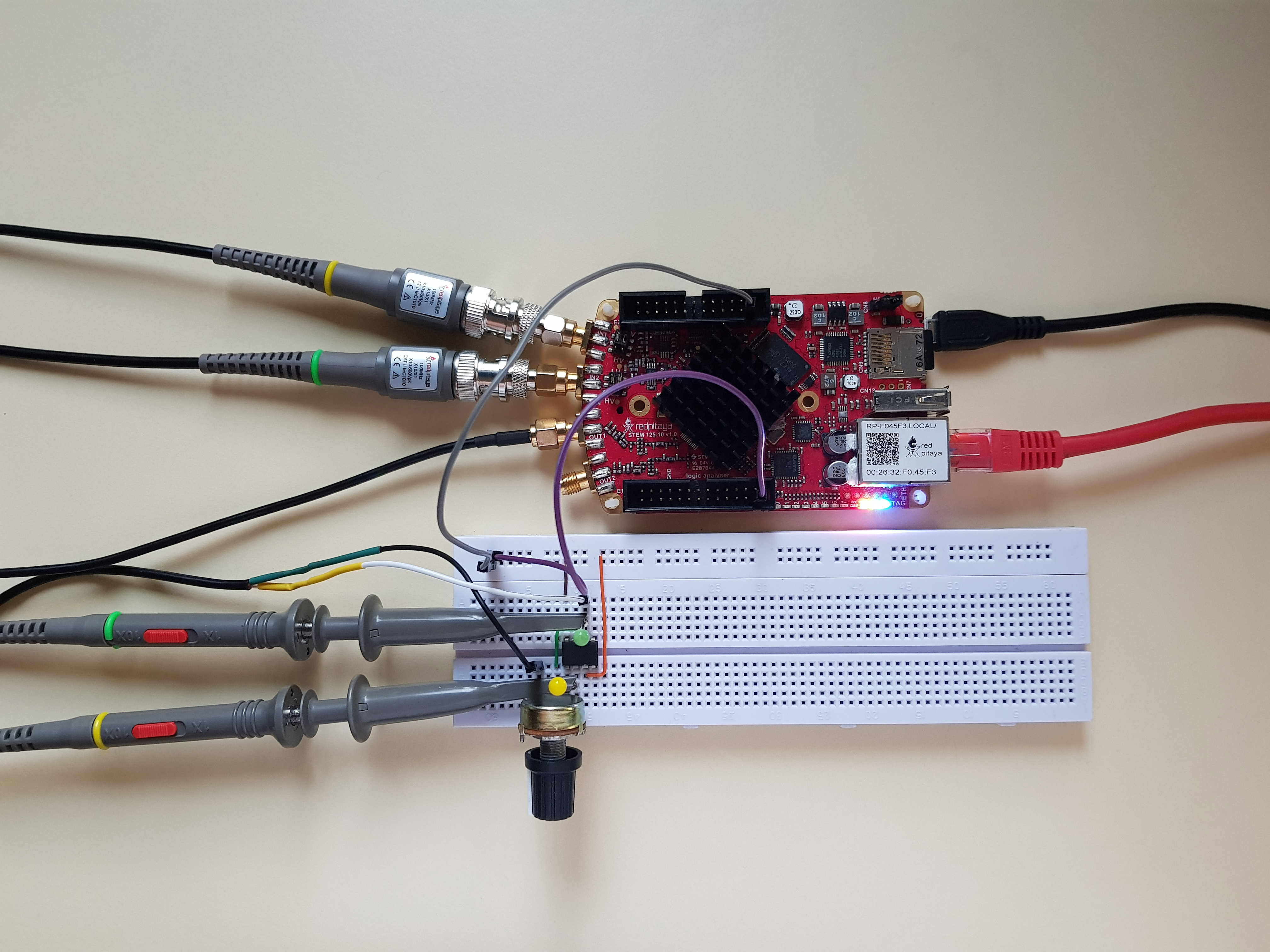
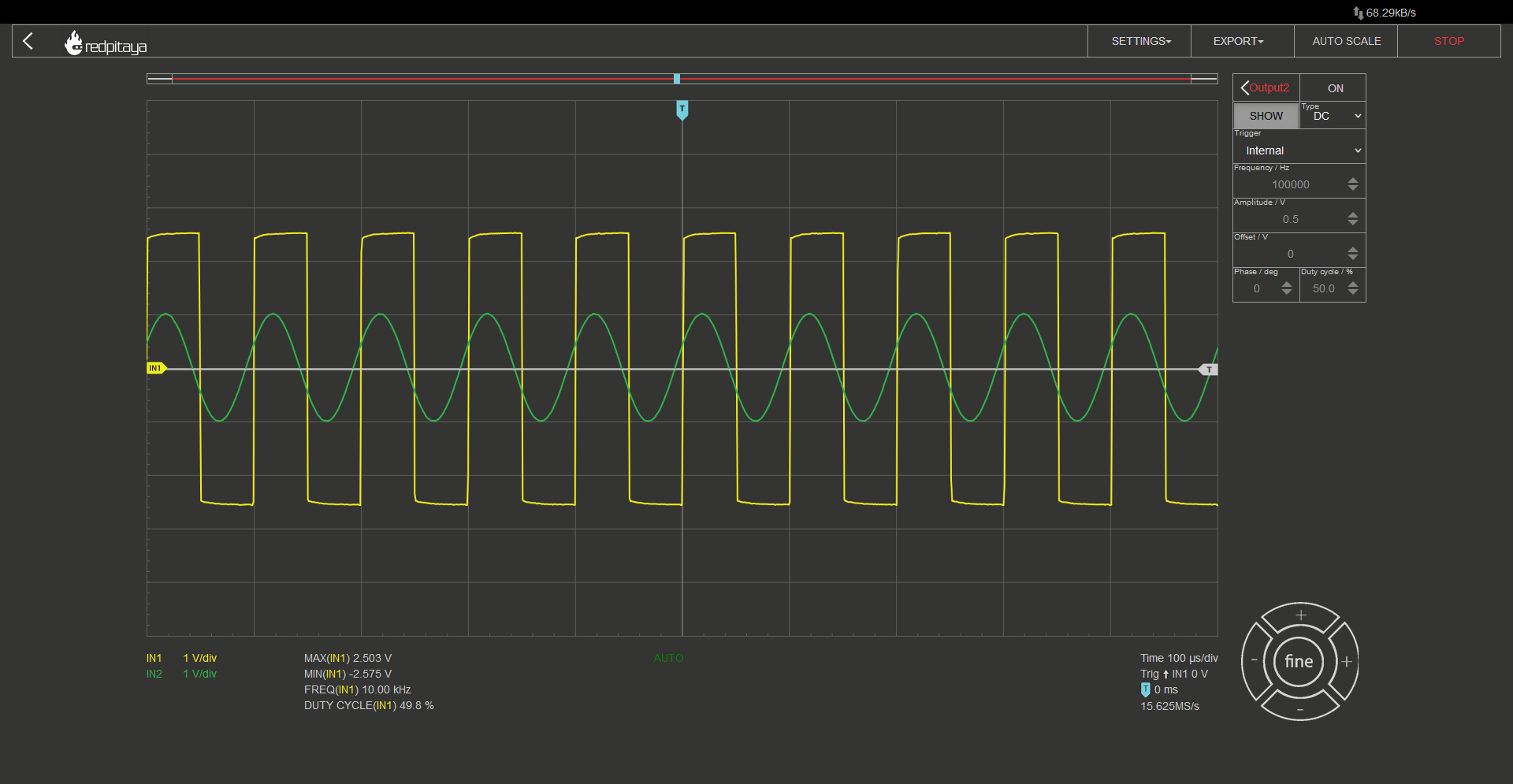
Now that we have a fundamental understanding of comparators, let’s conduct a simple experiment using an inverting comparator with the OP37 chip. We will power the OpAmp from a symmetrical +-3.3 V source instead of the usual +5 -3.3 V source. To conduct the experiment, we will set one of Red Pitaya’s outputs to output a DC voltage as our reference voltage, and the other output will generate a sine wave at the maximum amplitude as our input signal. By connecting one input probe to the comparator’s output and the other to the sinusoidal output, we can observe the output behavior as we modify the circuit. As expected, the output will be negative when the input is greater than the reference, and vice versa. I encourage you to follow along as this is a very straightforward experiment.
What would happen if we added a load resistor to the comparator’s output? Nothing. Probably because you forgot that the loads resistor has to be connected to the ground. But even if you connected the load resistor as one should, you should still see that the output voltage remains unchanged. Unless the resistor was very small and you would overload the comparator’s output stage. Now what would happen if we replaced this one resistor with a pair of them wired in series? And let’s make them a potentiometer so that we will be able to vary their ratio easily. Unsurprisingly, comparator’s output remains unchanged. From the comparator’s perspective a potentiometer is exactly the same as a simple resistor. However, here’s a clever trick: disconnect the reference voltage and disable the output, then connect the potentiometer’s wiper terminal to the noninverting input of the comparator. Depending on the position of the potentiometer, you may observe no change, everything may stop working, or something entirely different may happen. Turning the potentiometer will reveal both extremes.
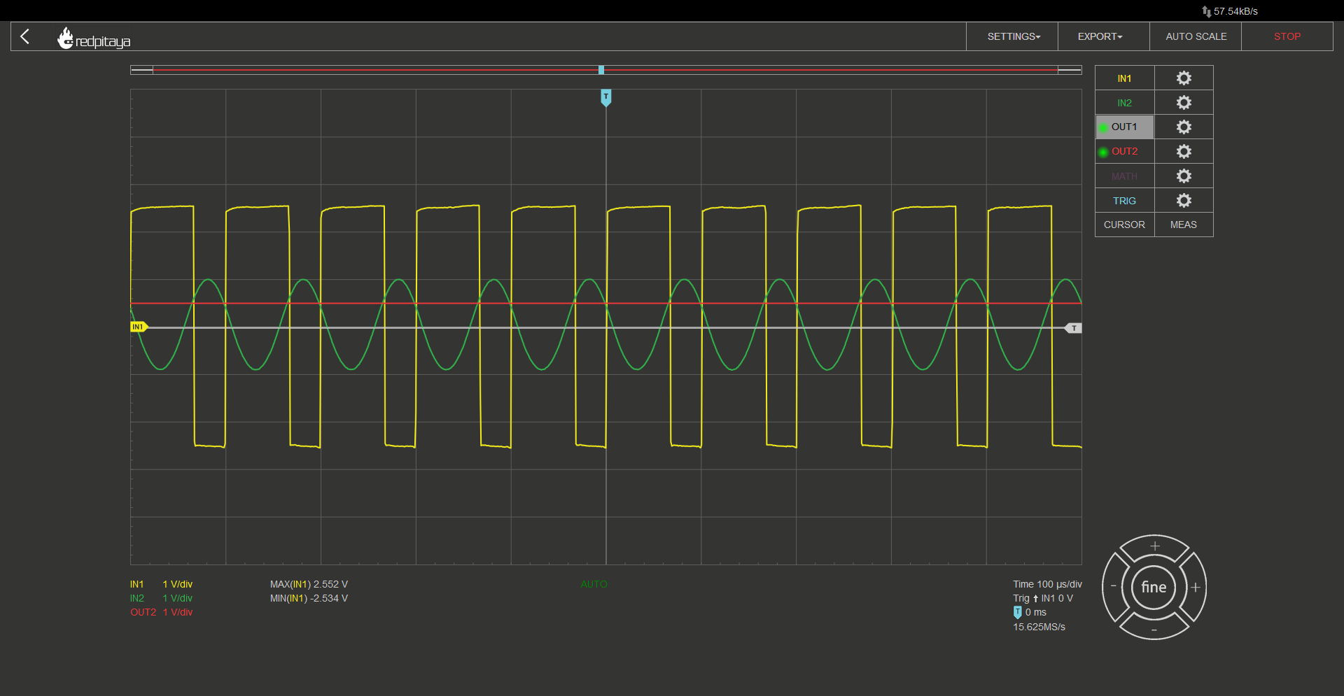
When this circuit operates in a manner similar to that of an inverting comparator, you will observe that the output becomes positive only after the sine wave becomes a bit negative, and the output becomes negative when the sine wave is a bit above zero. This behavior is characteristic of an inverting Schmitt trigger.
2.10.4. Schmitt trigger
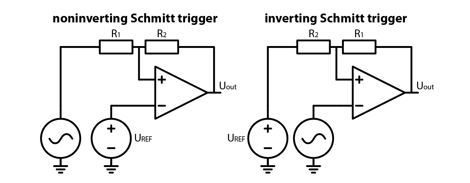
In case you found it hard to follow my circuit description of an inverting Schmitt trigger from before, here is a pair of schematics, one for an inverting and one for a noninverting Schmitt trigger. Note that we connected reference voltage to the ground potential.
So we’ve made an experiment, we’ve seen how a Schmitt trigger behaves and we’ve seen the schematics, but we still have to explain how a Schmitt trigger works. Quite the opposite to what we usually do. Coming up: explanation and the equations.
2.10.5. How it works: inverting Schmitt trigger
Let’s start off by looking at the inverting Schmitt trigger. Uout jumps between positive and negative saturation voltage. The resulting voltages on resistor divider are called high and low threshold voltages.
\[U_{TH}= U_{sat+} \cdot \frac{R_2}{R_1 + R_2}\]\[U_{TL}= U_{sat-} \cdot \frac{R_2}{R_1 + R_2}\]
Now let’s think about what happens during operation. Let’s assume that input is very low, far below comparator’s saturation voltage. This means that the comparator’s noninverting input is below 0 V and output will be positive. In order for output to toggle to negative saturation, input signal has to exceed \(U_{TH}\). Now that the output is at negative saturation, input has to fall below \(U_{TL}\) for the output to toggle again. Hard to follow? Take a glance at the diagram and corresponding oscillogram. Let’s consider the operation of the circuit. Suppose that the input voltage is very low, significantly below the comparator’s saturation voltage. This implies that the voltage at the noninverting input of the comparator is below 0 V, and the output of the comparator will be positive. To make the output switch to negative saturation, the input signal must exceed the value of the upper threshold voltage \(U_{TH}\). Once the output is at negative saturation, the input voltage must drop below the lower threshold voltage \(U_{TL}\) for the output to switch back to positive saturation. If you find this explanation difficult to follow, please refer to the diagram and oscillogram for a better understanding.

2.10.6. How it works: noninverting Schmitt trigger
Let’s now take a look at the noninverting Schmitt trigger, starting with toggle point voltages. Unlike before, where noninverting input was just saturation voltage, divided by a resistor divider, here the voltage at the noninverting input is a function of input voltage. Switch happens, when this voltage crosses 0 V. Threshold voltages in this case are such:
\[U_{TH}= -U_{sat-} \cdot \frac{R_1}{R_2}\]\[U_{TL}= -U_{sat+} \cdot \frac{R_1}{R_1}\]
Instead of walking you through the thought experiment of how and why a noninverting Schmitt trigger works, let me just show you the diagram and the oscillogram.

2.10.7. Schmitt trigger instead of a comparator. Why?
Let me answer with a graph:
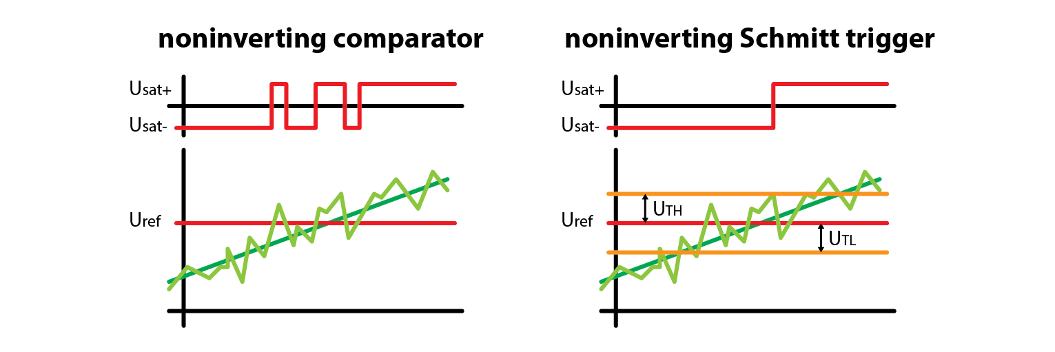
A signal with noise can cause multiple output transitions in a regular comparator, while a Schmitt trigger with properly adjusted hysteresis can avoid this issue. It’s important to note that a Schmitt trigger is designed to have a delayed transition due to the offset of threshold voltages from the reference voltage. Therefore, comparators are still frequently used. Additionally, if the noisy component is at a high frequency, it may not cause false transitions since the comparator requires some time to switch the output.
2.10.8. Extra credits
Remember how I told you that I connected OpAmp to +- 3.3 V? That was done so that saturation voltages were +- 2.6 V. What would happen if saturation voltages weren’t the same?
2.10.9. Conclusion
Schmitt triggers are an essential building block for signal conditioning in analog-to-digital interfaces, and their simplicity makes them an attractive choice for many applications. By using just a comparator and two resistors, a Schmitt trigger can provide hysteresis to ensure reliable switching of signals in the presence of noise or other disturbances. So, if you want to deepen your understanding of analog circuits and their practical applications, replicating the experiments from this course is a great place to start. And here’s a little teaser for you: the next course will continue where we left off today, delving deeper into the world of analog circuits and exploring some more advanced topics. So, if you’re curious about what’s coming next, be sure to stay tuned!
Written by Luka Pogačnik Edited by Andraž Pirc
This teaching material was created by Red Pitaya & Zavod 404 in the scope of the Smart4All innovation project.