2.4. OpAmps 101
2.4.1. Objective
The objective of this activity is to introduce the reader to a very useful yet not that well known type of electronic components, the operational amplifiers.
2.4.2. Background
Operational amplifiers, or OpAmps, are electronic components that contain a chunk of doped silicon comprised of several transistors, resistors, and capacitors, hidden within their package. They feature two power pins, two input signal pins, and one output pin. Unlike regular differential amplifiers, OpAmps exhibit very high gain and fast response time, making them suitable for various applications beyond their apparent purpose. These components are configured in a way that results in the output pin producing the voltage difference between the two input pins, multiplied by a significant factor. However, their high gain makes them unsuitable as a differential amplifier.
2.4.3. How it works
OpAmps have two input pins, called inverting (-) and noninverting (+), which should not be confused with the power supply pins. The power supply pins are the positive and negative supply pins, which may be labeled with + and - signs or V+ and V-, and are used to power the OpAmp. OpAmps also have an output pin, and some chips may have additional connections for offset voltage compensation.
It is important to note that the negative supply pin of an OpAmp is not meant to be connected to ground, and the positive supply pin is not meant to be connected to the supply voltage. Instead, OpAmps are typically connected between a positive and negative voltage, with the negative voltage being below ground potential, such as the -4 V pin on the Red Pitaya.
The output pin of an OpAmp is equal to the difference between the noninverting and inverting inputs, multiplied by a large gain factor known as the “open loop gain” (A_OL), which can be as high as 100,000.
\[U_{OUT}=A_{OL} \cdot (U_+-U_-)\]
Such a large gain means, that output would exceed supply voltage for even a very small difference between input voltages; even some noise, that gets coupled to inputs, may send the output into saturation. What is saturation? Saturation is what happens when OpAmp’s output hits the limits of how far it can go. And how far is it? Usually from a few volts above negative supply voltage up to a few volts below positive supply voltage. There are some OpAmps who’s output can swing from negative to positive supply voltage. Those are called rail-to-rail OpAmps. And just to make it clear: when OpAmp hits saturation, output gets clamped.
2.4.4. The symbol
OpAmps are available in a variety of package types, but their symbols have been standardized for conveying their functions and for creating electrical schematics for PCB production. The symbol for functional representation does not include power pins, while the schematic representation does. There are additional pins for offset compensation, differential outputs, and other features that are not discussed in this introductory article. It is worth noting that the symbols for OpAmps and comparators are nearly identical, as the two components have similar construction and functions.

Now that we’ve discussed the symbol, it is time to take a look at what can what functions an OpAmp can be used for.
2.4.5. A comparator
Comparators are specialized amplifiers designed to compare two voltages and output a digital signal indicating which input is higher. They are commonly used in applications such as analog-to-digital converters, level detectors, and pulse generators. Unlike op-amps, comparators have a very fast response time and are optimized for speed rather than accuracy.
While comparators can be bought as a separate component, op-amps can also be used as comparators by connecting the output to a voltage rail instead of a feedback resistor. Whenever the voltage at the non-inverting input exceeds the voltage at the inverting input, the output will saturate to the positive rail. Conversely, when the voltage at the inverting input exceeds the voltage at the non-inverting input, the output will saturate to the negative rail. However, it is important to note that comparators have a larger output swing than op-amps and are better suited for high-speed applications.
2.4.6. A voltage follower
Let’s make a thought experiment. If we connected OpAmps output to its inverting input, and noninverting input to some arbitrary voltage. What would the output voltage be?

In the previous chapter, we discussed the instability issues when using a comparator instead of an OpAmp. When the output of a comparator is above U+, it hits negative saturation, and when it is below U+, it hits positive saturation. This behavior is not suitable for applications that require stability. In contrast, OpAmps have a slower response time, making them more resistant to becoming unstable. In most OpAmp circuits, when working within voltage limits, the output is equal to the input voltage.
The usefulness of this feature comes from the fact that OpAmps have a large input impedance and a small output impedance. This property allows us to connect OpAmp inputs to any node in a circuit without affecting it, as long as the node’s voltage is within the OpAmp’s safe operating range. Additionally, we can connect the OpAmp output to any load, as long as the current draw doesn’t exceed the OpAmp’s rating. This feature is especially helpful in applications such as analog filters, where we want to connect a load to a circuit without affecting it.
2.4.7. An amplifier
Suppose that you desired to amplify the input voltage by a smaller factor, rather than the tens or hundreds of thousands commonly achieved by OpAmps. How would you approach this task?

Let’s analyze why this circuit works. Assuming the OpAmp is not saturating, the inverting and noninverting inputs will be at the same potential, which is indicated by a dashed line. It should be noted that the inputs are not physically connected. Now, let’s examine the equations:
\[(U_{OUT}-0V) \cdot \frac{R_1}{R_1+R_2}=U_{IN}\]
Resistors 1 and 2 form a resistive voltage divider for output voltage. Obviously Output voltage will have to be greater than input, otherwise original assumption, that both inputs are at the same potential, would be false. If we flip around the equation to express exactly what output voltage should be, we get:
\[U_{OUT}=U_{IN} \cdot (1+\frac{R_2}{R_1} )\]
Given the equation for the amplifier circuit, it is clear that the output voltage cannot be less than the input voltage if the OpAmp is not hitting saturation. To verify this claim, we can analyze the circuit and confirm that the voltage gain is always greater than or equal to 1.
2.4.8. An inverting amplifier
Given that an OpAmp can be used for signal amplification and has an input called the “inverting input,” it follows that there exists a specific circuit configuration called the “inverting amplifier.” This configuration is widely used in electronics and serves to amplify an input signal with an amplification factor that is determined by the ratio of two resistors in the circuit. The inverting amplifier is a type of operational amplifier circuit that produces an output that is proportional to the negative of its input.

Once again, starting assumption is that both inputs are at the same voltage. I trust you would be able to derive the formula for output voltage as the approach is the same as before, but if you’ll want to verify your calculations, here is the setup:
\[(U_{OUT}-U_{OUT}) \cdot \frac{R_1}{R_1+R_2}=0V\]
And if we express output voltage as a function of input voltage:
\[U_{OUT}=-V_{IN} \cdot \frac{R_2}{R_1}\]
In this configuration, output voltage will always have an inverse sign than input, but its absolute value may be amplified or attenuated. Now that we went through all basic OpAmp circuits, let’s verify that the amplifiers actually behave the way I described.
2.4.9. A non-inverting amplifier - the experiment
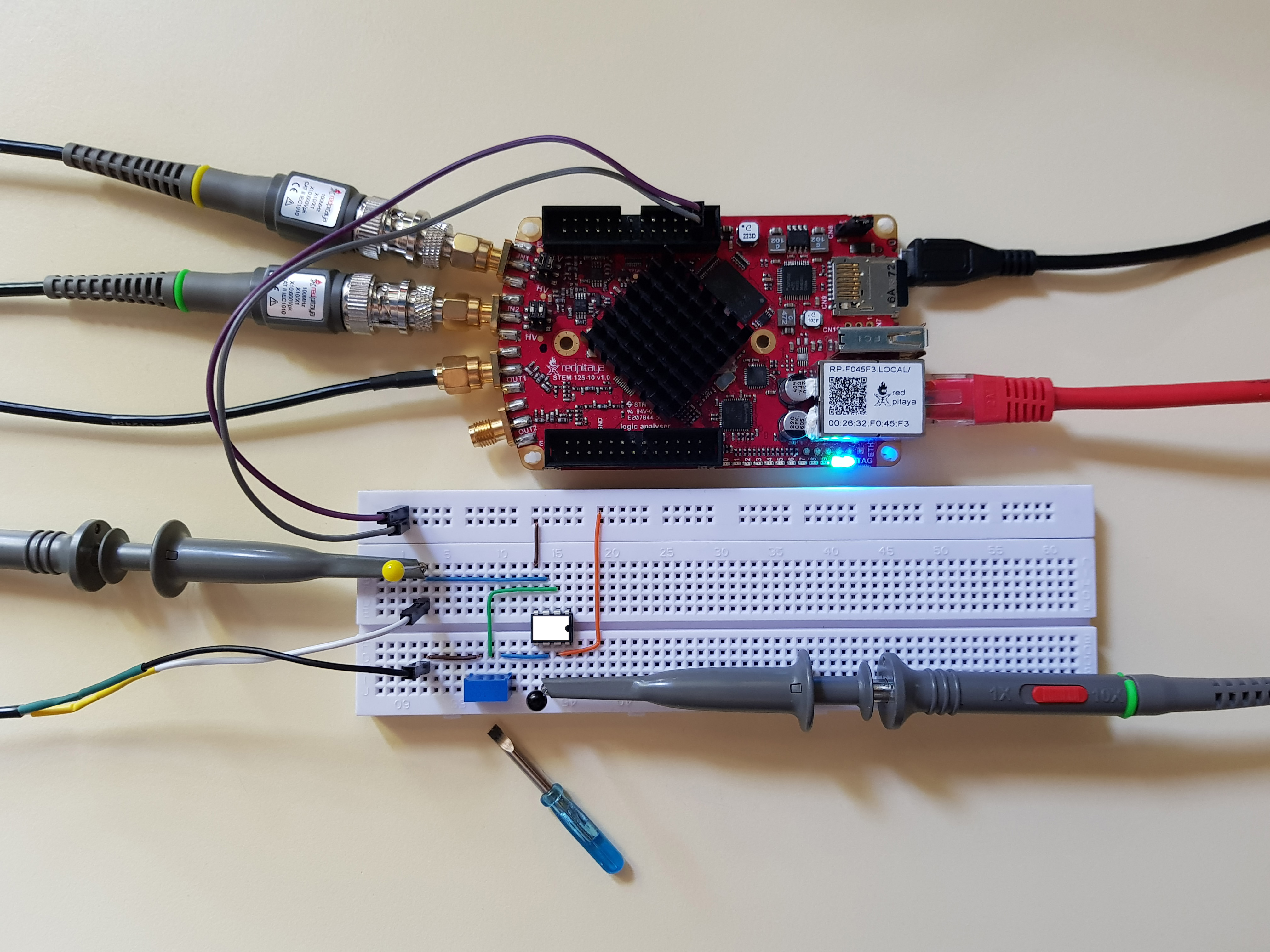
First thing that we will need is an OpAmp. I have decided to use OP37. Why? There are two in the ADALP2000 Analog Parts Kit (the kit this entire set of courses is designed around) so ye can fry one without worrying too much. Here is the chip’s pinout:

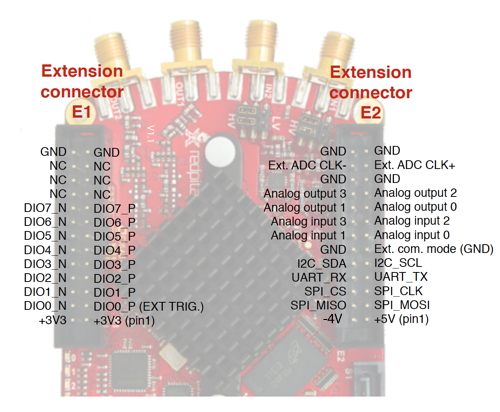
Connect U+ to Red Pitaya’s 5V pin and U- to -4V pin. Inputs and output will be connected as per schematic, and the rest (pins with greyed out names) will remain unconnected.
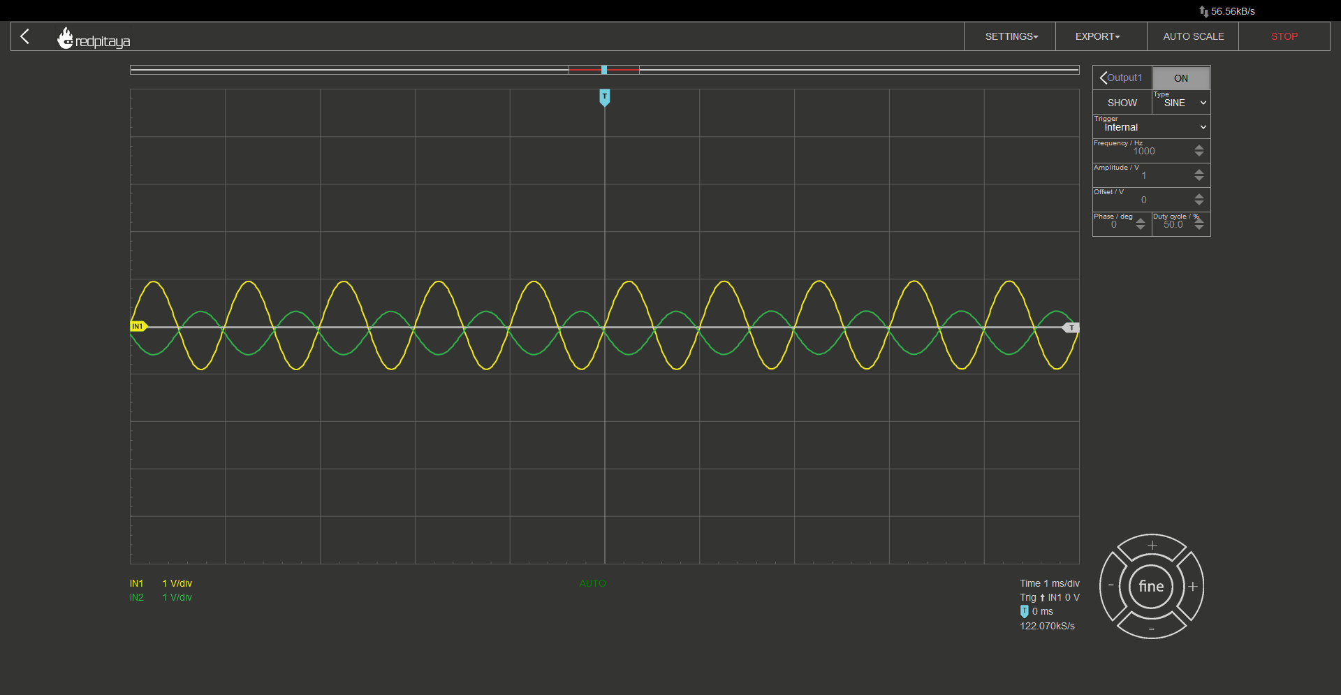
The one difference I made is that I used a potentiometer instead of two separate resistors for R1 and R2. This way I can easily vary resistor ratio. Since this is the most complex circuit so far, I made sure to wire it cleanly so that you can follow the wiring more easily. For those wondering: Connections were made using wires from Ethernet cables. CAT6 works the best. Let’s now connect everything up. All probes in x10 mode, one on input, one on output. Let the Red Pitaya generate a sine wave and connect it to the amplifier’s input. For those playing along at home, I encourage you to turn the potentiometer and observe what happens with the output. What is the maximum amplification? When do you hit Saturation? Are inverting and noninverting inputs really at the same voltage? How about when OpAmp hits saturation? Unfortunately, I can’t show how I turn the potentiometer in this writeup but you can experiment at home, or watch the accompanying video.
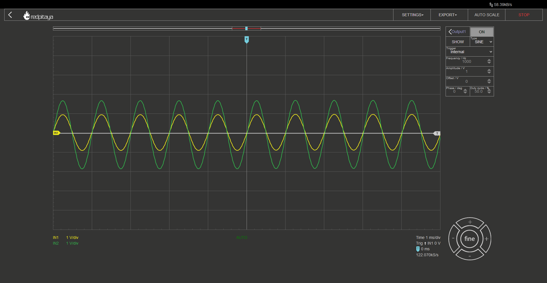
If you followed the diagram correctly, you should see something like this on the screen. At least if you didn’t forget to enable the signal generator and if resistor divider is within what OpAmp can handle.
As a side note I would like to mention that a voltage follower is “just” an extreme variant of an OpAmp amplifier, where R2 equals 0 ohms and R1 is infinite.
2.4.10. An inverting amplifier - the experiment
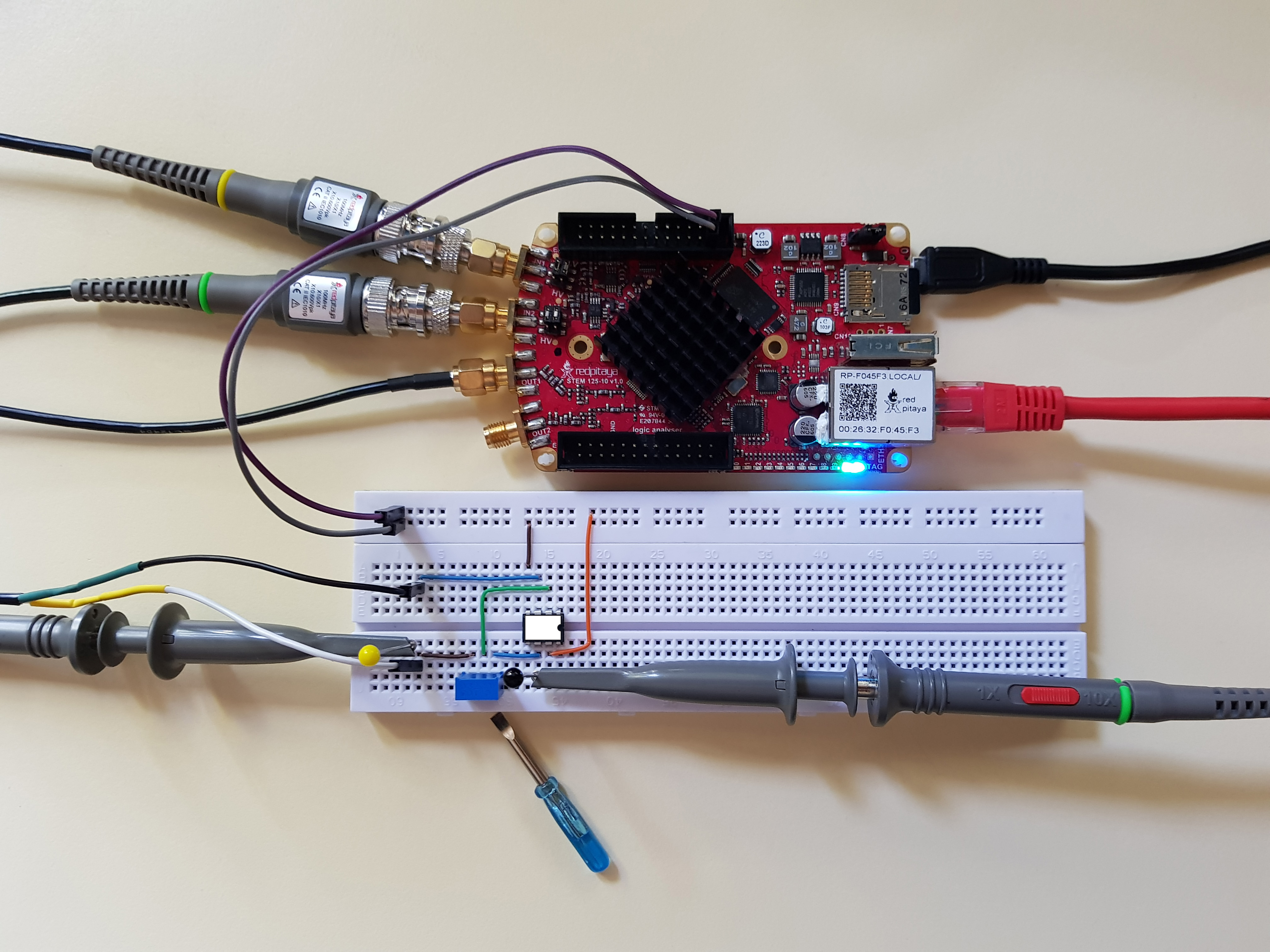
This experiment will be the same deal as before. I made sure to make the wiring as clear as possible, and used a potentiometer instead of two discrete resistors. Here is the circuit:
I would once again encourage you to see what happens when you turn the potentiometer. Try to make predictions. Maybe measure signal amplitudes and calculate resistor ratio. You can then plug the potentiometer out and measure resistances to verify your calculations.
2.4.11. Conclusion
If you read through the entire article, you are now familiar with the four most common (or at least beginner-friendly) applications for operational amplifiers: comparator, voltage follower and two types of amplifiers. If you also followed along with the experiments, you may have gotten a feeling for distortions you will encounter when amplifier is operating close to or beyond saturation. In any case I hope You found this article both interesting and fun. The question I would like to leave you with is: how would you build a noninverting amplifier with attenuation (gain between 0 and 1)?
Written by Luka Pogačnik Edited by Andraž Pirc
This teaching material was created by Red Pitaya & Zavod 404 in the scope of the Smart4All innovation project.