1.3.2. Programming the FPGA
After the installation of Vivado, we will have to clone the FPGA repository and edit an existing project for our “Hello World” (Blink) project.
1.3.2.1. Clone FPGA GitHub repository
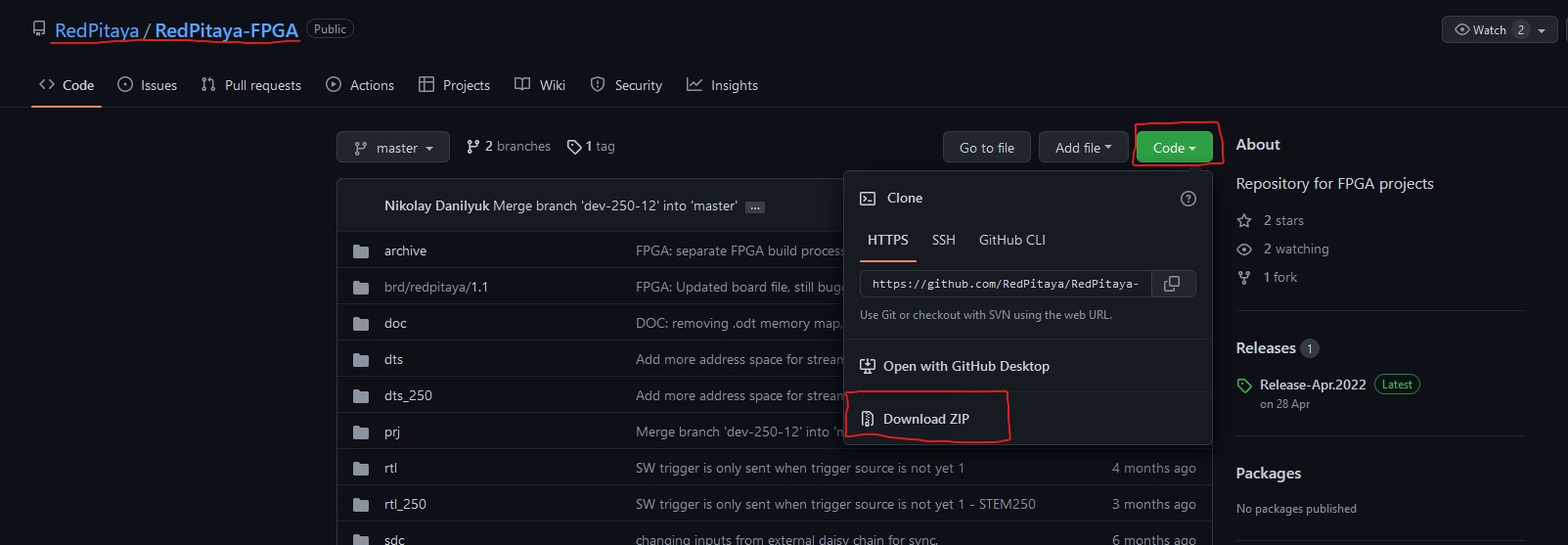
Go to the Red Pitaya FPGA Github site and download the ZIP folder of this project.
If you are using Windows, download the project repository and extract it to a folder of your choice. Remember the path to the location of the extracted repository (when you will be searching for your disk location in the WSL, go to the root directory and move into the mnt directory).
Alternatively, if you are using Linux or WSL, you can first install git, then move to a desired location and make a clone of the Red Pitaya Git repository:
sudo apt-get install git
git clone https://github.com/RedPitaya/RedPitaya-FPGA.git
1.3.2.2. Make an FPGA project
Go to the downloaded Red Pitaya FPGA Repository ZIP location and extract it to a folder/directory on your computer.
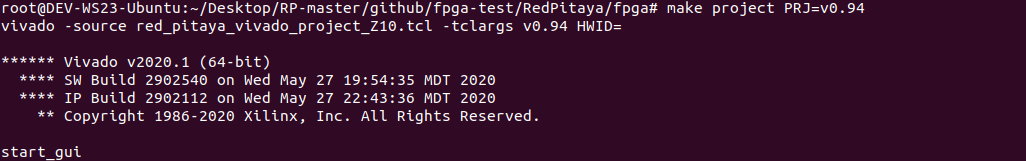
Open Vivado and using the TCL console navigate to the extracted folder and make a Vivado project.
. /opt/Xilinx/Vivado/2020.1/settings64.sh
cd Downloads/
cd RedPitaya-FPGA/
make project PRJ=v0.94 MODEL=Z10
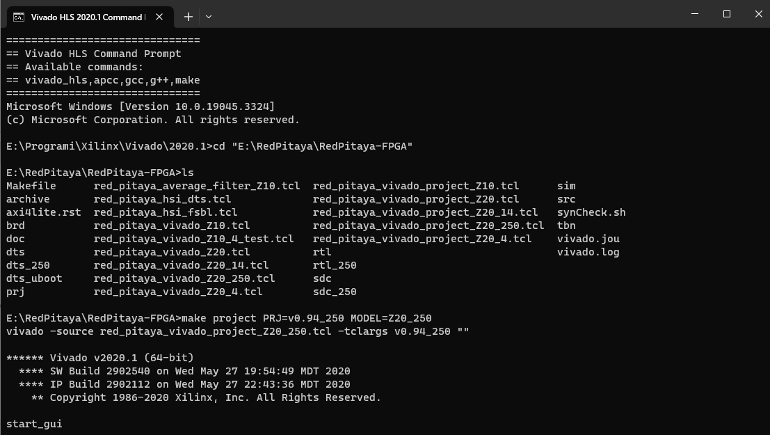
Open Vivado, and using the TCL console, navigate to the extracted folder and make a Vivado project. Alternatively, search for Vivado HLS 2020.1 Command Prompt and launch it.
Navigate to the extracted folder and make a Vivado project:
cd Downloads/
cd RedPitaya-FPGA/
make project PRJ=v0.94 MODEL=Z10
Note
The instructions above are an example for how to create an empty v0.94 project for STEMlab 125-14. For other boards, please use the flags in the table below. For more information on alternative Project flag options options, please refer to Developers Guide Software.
Table of required build flags for the recommended v0.94 FPGA project per board:
Model |
Build Project flag |
Build Model flag |
|---|---|---|
STEMlab 125-10
STEMlab 125-14
|
PRJ=v0.94 |
MODEL=Z10 |
STEMlab 125-14-Z7020 |
PRJ=v0.94 |
MODEL=Z20_14 |
SDRlab 122-16 |
PRJ=v0.94 |
MODEL=Z20 |
SIGNALlab 250-12 |
PRJ=v0.94_250 |
MODEL=Z20_250 |
STEMlab 125-14 4Ch Z7020 |
PRJ=v0.94 |
MODEL=Z20_4 |
For this project, you will only have to edit the red_pitaya_top.sv file. Edit the port led_o assignment at the beginning of the file. Change the port to output logic.
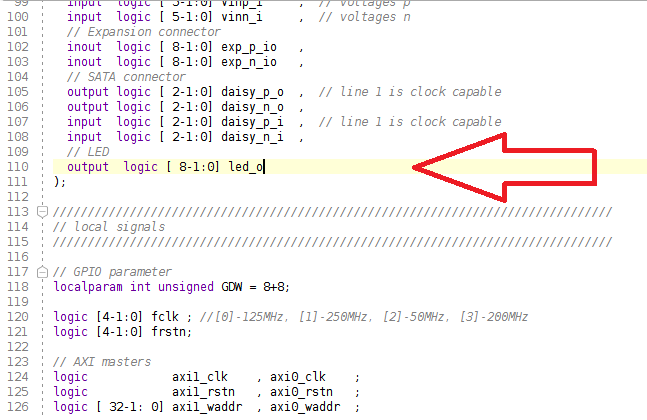
Now, in this section of the file, comment out the led_o port.
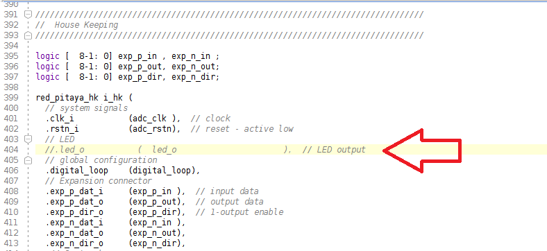
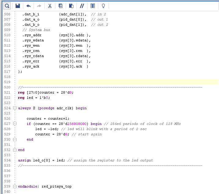
Finally, insert this code at the end of the module, before endmodule: red_pitaya_top. It will make the LED blink.
reg [27:0]counter = 28'd0;
reg led = 1'b0;
always @ (posedge adc_clk) begin
    counter = counter+1;
    if (counter == 28'd256000000) begin      // 256e6 periods of clock of 125 MHz
        led = ~led;                          // led will blink with a period of aprox. 2 sec
        counter = 28'd0;                     // reset the counter
    end
end
assign led_o[0] = led;                       // assign the register value to the led output
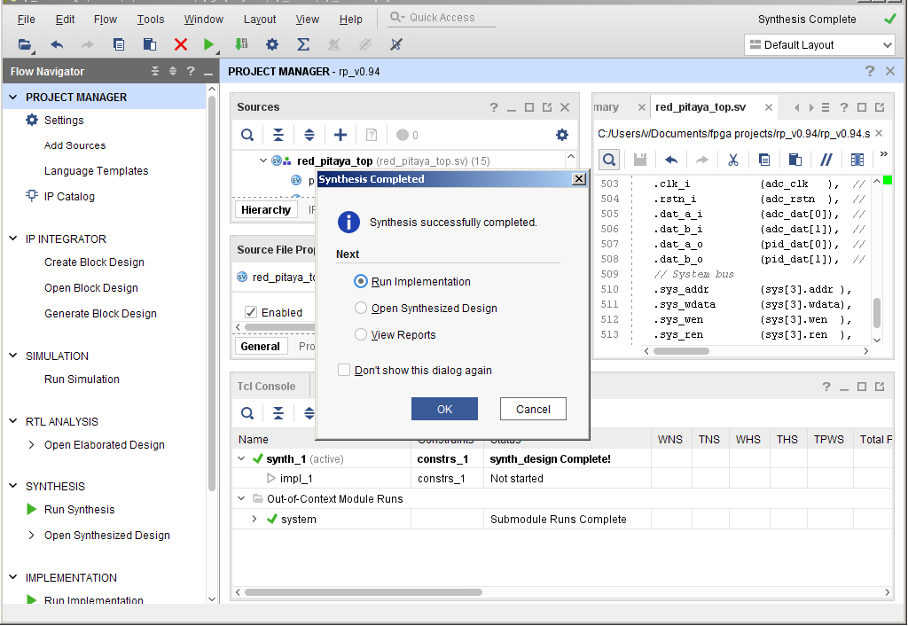
Now you have to start synthesis, implementation, and writing a bitstream. Press the button to start the synthesis. You can also just click on the “Generate bitstream” and all the steps will execute automatically.

After synthesis is finished, start implementation.
Implementation finished. Start writing the bitstream.
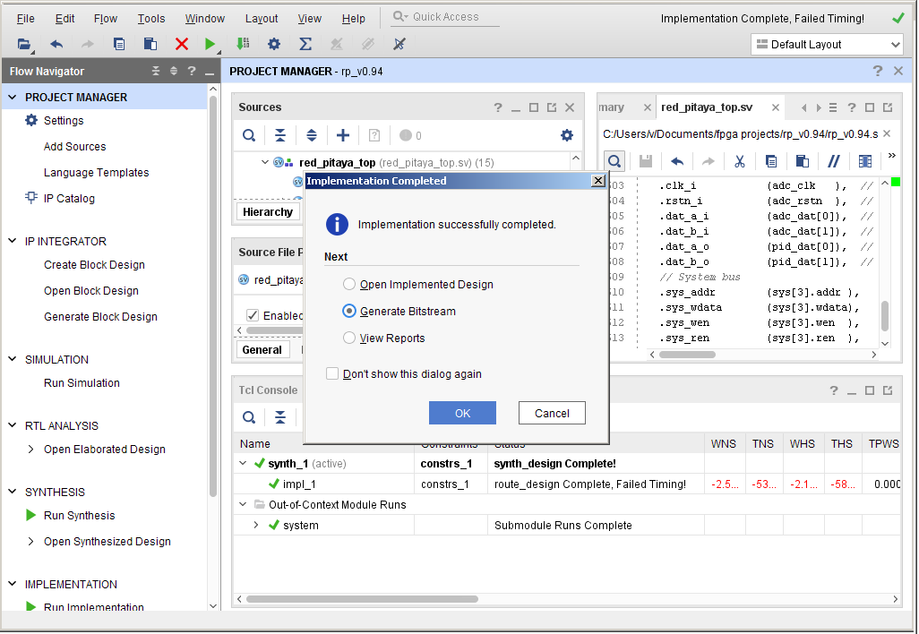
The bitstream file red_pitaya_top.bit is located in …/prj/v0.94/project/repitaya.runs/impl_1
You have to send this file to your Red Pitaya board. Open a terminal and connect to your Red Pitaya using an SSH connection. Also, enable the read/write operation on the Red Pitaya. To establish the connection you can either use your Red Pitaya’s IP address or the “rp-xxxxxx.local”, where “xxxxxx” are the last six characters of the MAC address.
ssh root@rp-xxxxxx.local
redpitaya> rw
1.3.2.2.1. Reprogramming the FPGA
How the FPGA is reprogrammed depends on the Red Pitaya OS version.
Please make sure that the PATH environment variable is set correctly. See Vivado installation guide for more information.
Note
On Windows, the easiest way is to perform the process inside Vivado’s TCL console. The process can also be done through a standard Command Prompt, but any echo commands must be executed inside the Windows Subsystem for Linux (WSL) Terminal (The output file encoding is a problem with Windows echo). For more information, refer to the following forum topics:
Please note that you need to change the forward slashes to backward slashes on Windows.
Open Terminal or CMD and go to the .bit file location.
cd <Path/to/RedPitaya/repository>/prj/v0.94/project/repitaya.runs/impl_1
Send the file .bit (red_pitaya_top.bit is the default name) to the Red Pitaya with the
scpcommand.
scp red_pitaya_top.bit root@rp-xxxxxx.local:/root
Now establish an SSH communication with your Red Pitaya and check if you have the copy red_pitaya_top.bit in the root directory.
redpitaya> ls
Load the red_pitaya_top.bit to xdevcfg with
redpitaya> cat red_pitaya_top.bit > /dev/xdevcfg
The 2.00 OS uses a new mechanism of loading the FPGA. The process will depend on whether you are using Linux or Windows as the echo command functinality differs bewteen the two.
Please note that you need to change the forward slashes to backward slashes on Windows.
On Windows, open Vivado and use the TCL console. Alternatively, use Vivado HSL Command Prompt (use Windows search to find it). Navigate to the .bit file location.
On Linux, open the Terminal and go to the .bit file location.
cd <Path/to/RedPitaya/repository>/prj/v0.94/project/repitaya.runs/impl_1
Create .bif file (for example, red_pitaya_top.bif) and use it to generate a binary bitstream file (red_pitaya_top.bit.bin)
Windows (Vivado TCL console or Vivado HSL Command Prompt):
echo all:{ red_pitaya_top.bit } >  red_pitaya_top.bif
bootgen -image red_pitaya_top.bif -arch zynq -process_bitstream bin -o red_pitaya_top.bit.bin -w
Linux and Windows (WSL + Normal CMD):
echo -n "all:{ red_pitaya_top.bit }" >  red_pitaya_top.bif
bootgen -image red_pitaya_top.bif -arch zynq -process_bitstream bin -o red_pitaya_top.bit.bin -w
Using a standard command prompt, send the file .bit.bin to the Red Pitaya with the
scpcommand.scp red_pitaya_top.bit.bin root@rp-xxxxxx.local:/root
Now establish an SSH communication with your Red Pitaya and check if you have the copy red_pitaya_top.bit.bin in the root directory.
redpitaya> lsLoad the red_pitaya_top.bit.bin image into the FPGA:
redpitaya> fpgautil -b red_pitaya_top.bit.bin
After executing the last command, you should see an LED blink. Congratualtions on writing your first FPGA program!
1.3.2.2.2. Reverting to original FPGA image
If you want to roll back to the official Red Pitaya FPGA program, run the following command:
redpitaya> cat /opt/redpitaya/fpga/fpga_0.94.bit > /dev/xdevcfg
redpitaya> overlay.sh v0.94
or simply restart your Red Pitaya.